How CAN SIC Limits Signal Ringing in CAN Networks

What you'll learn:
- What is CAN SIC?
- Why is signal ringing such a critical factor in networking?
- Besides automotive, what other applications can take advantage of CAN SIC?
- What's the relationship between CAN FD and CAN SIC?
ED: You’re working on a technology called CAN Signal Improvement Capability (SIC). What is it and why is it needed?
Teun Hulman: CAN was developed as a bus communication technology for the automotive industry in the early 1990s, allowing 500-kb/s communication between nodes in the bus network. Over time, the network and the number of nodes in a vehicle grew rapidly to support new applications in the car.

Along with these new applications came an increased demand for higher bandwidth communication on the CAN bus. The introduction of CAN with Flexible Data Rate (FD) was intended to solve this need by introducing data rates of up to 5 Mb/s, effectively allowing OEMs to increase the bandwidth on these larger networks.
But this wasn’t enough when it came to data-rate requirements?
That’s right, CAN FD quickly reached its limits because the higher data rates could only be achieved by limiting the network size. The limiting factor for CAN FD has been the effect of so-called signal ringing on the CAN communication.
What is signal ringing?
Signal ringing is an artifact of reflections, caused by impedance mismatches in the network. It occurs when cables branch throughout the network and thus becomes increasingly more present in complex networks. The ringing disturbs the signals traveling over the bus, and the result is that you cannot reliably determine the unstable signal’s actual level until the ringing has dissipated.
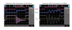
Ringing has always been present in CAN networks, but as the introduction of higher data rates require shorter bit times, the time for ringing to dissipate is limited (Fig. 1). Therefore, high-speed networks can only tolerate minor ringing if they are to operate reliably. This creates a tradeoff between achievable data rate and topology complexity.
Why is finding a solution to signal ringing important?
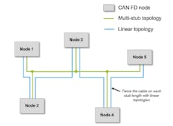
Today’s CAN FD networks use highly linear topologies to avoid any long cable branches that might generate signal ringing. The problem with this approach, however, is that it’s very inflexible and creates much more cabling, which adds cost and weight to, for example, a vehicle.
Linear topologies pose several additional restrictions and design overhead, mainly related to managing the diversity of network applications and variants (Fig. 2). To accommodate different topology configurations and support design flexibility, multiple cable harnesses need to be designed and maintained, making linear networks more inflexible.
Solving signal ringing will allow network architects to create the networks they want, both in terms of their preferred topology and the data rate required for their application
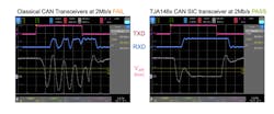
This is where CAN Signal Improvement Capability, or CAN SIC, comes into the picture. It solves the tradeoff between topology and data rate by actively removing the signal ringing from the network (Fig. 3). In addition, it boosts performance to enable communication up to 8 Mb/s. This gives OEMs more flexibility to design networks to fit their requirements, while allowing them to take the next step in data throughput. Also, by increasing the maximum data rate to 8 Mb/s, CAN SIC is positioned as relatively less expensive than other technologies.
Is it possible to implement CAN SIC retrospectively and, if so, do you think anyone will do that?
It is. We were able to design CAN SIC as a drop-in replacement for existing CAN solutions. That makes it possible to implement CAN SIC retrospectively, without the hassle of changing your design. Customers can use their existing network designs and benefit from the increase in data rates and higher-reliability communication. This also could allow them to implement cheaper cables or optimize their network to reduce complexity or increase flexibility.
Is CAN SIC targeted solely at the automotive market?
Although CAN SIC was originally developed for automotive, the benefits apply to CAN networks in other industries, such as industrial automation, robotics, and the IoT.
Industrial CAN networks generally cover much longer distances than a vehicle, meaning that the problem of signal ringing hampering efficient network designs may end up being even more costly. CAN SIC is able to unlock new ways for designers to reduce cable costs. Or you can use it to achieve a higher data rate on the same harness.
Furthermore, existing cables might be fixed in place—for instance, routed through the walls or floors of a factory—making them expensive to upgrade or adapt. With CAN SIC transceivers, it’s possible to increase the data rate of the network without having to modify the physical cabling.
Warehouse robots, drones, and other systems face the same sort of network issues as automobiles do, including limited routing space and weight constraints. Despite the relative short distances between nodes, the complexity of the network can grow due the need for redundancy—a secondary network that can be engaged in the event the primary network fails. CAN SIC aims to optimize both the primary and redundant network for cost, weight, and data rate.
Removing signal ringing from the network CAN SIC also enables more flexibility in bus termination. Standard CAN FD requires dual termination, preferably at the end nodes of a network to guarantee signal integrity. CAN SIC could enable a single termination at a central node, facilitating a simplified overall electronic control unit (ECU) design with standard end nodes.
On top of that, CAN SIC offers improved electromagnetic compatibility (EMC) performance compared to standard CAN transceivers. This makes it a fit in applications with high interference levels and enclosed metal casings, such as UAVs.
Are changes required at the software/firmware level to implement CAN SIC?
In principle, no. CAN SIC is a drop-in replacement to a standard CAN transceiver, making upgrading very simple. Due to the backwards compatibility to the existing CAN standard and interoperability with standard CAN transceivers, no additional software or silicon should be needed.
How will NXP and other vendors bring CAN SIC to market?
NXP is deploying CAN SIC technology in the new TJA146x CAN SIC transceiver family. The family spans a Standby Mode transceiver (TJA1462) and a Sleep Mode transceiver (TJA1463), both of which come in SO and HVSON packages. This is a first generation of devices to cover the most common automotive and industrial uses, but our expectation is that this technology will expand into a wider range of products in the near future.
Is CAN SIC covered by a standard?
Yes, it is. We determined the best way for the market to take full advantage of CAN SIC was to standardize it. In cooperation with other industry stakeholders, NXP defined the CiA-601-4 standard, which prescribes the functional description, timing behavior, and EMC performance of CAN SIC.
Standardization creates a clear definition of CAN SIC and its requirements, and functions as a guideline for users and suppliers. This helps other semiconductor suppliers develop and offer interoperable devices with this technology as well.
Would automotive OEMs need to have their systems tested differently if they implement CAN SIC (instead of CAN FD, for instance)?
No. CAN SIC has been designed to fit into the standard network testing and development process, so no additional steps are needed for implementation. Network architects today typically simulate their network to ensure reliable operation with respect to signal ringing. The same method can be used to show the improvements of CAN SIC transceivers in the network.
NXP has worked with many customers and OEMs on testing and employing CAN SIC and offers simulation services to assess different topologies. This also helps them identify further improvements that can be made to their network designs to maximize the impact of this technology.
NXP’s CAN SIC solution is fully compliant to industry-standard EMC and ESD tests for CAN, meaning there are no changes in testing.
Can you explain where you think CAN Signal Improvement Capability fits in the networking landscape with CAN XL coming down the pipeline?
CAN SIC extends the potential of CAN FD—without requiring new microcontrollers or software changes. It is just a simple replacement to the CAN transceiver.
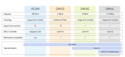
CAN XL is still in the definition and development phase. Looking ahead, though, CAN XL is planned to push data rates to more than 10 Mb/s while supporting up to 2048 bytes of payload (Fig. 4). That will exceed the potential of CAN SIC, but use of CAN XL will require new microcontrollers that support the protocol. As a result, an extensive upgrade of all ECUs on a network will be needed to run CAN XL.
One of the privileges of CAN SIC is that it works with existing MCUs, which makes upgrading to CAN SIC much easier. This means customers can remain with CAN FD longer, while still increasing performance, ultimately adding longevity to their installed base.
You describe CAN Signal Improvement Capability as “actively improving the CAN signal.” What do you mean by “actively” improving it? That implies some modification is made to the signal, which would suggest some hardware (either active or passive) is required.
NXP’s CAN SIC solution is based on a new high-performance transmitter. From the application’s standpoint, it works exactly like a standard CAN transceiver, following the digital transmit input pin. To the outside world, the signals still look like any other transceiver, guaranteeing that they fully conform to the CAN standard. However, the new transmitter takes more precise control of the CANH and CANL signal. As a result, the way in which the transmitter drives the signal is a very different and active process.
This has two major advantages:
- Tighter timing specifications of the transceiver, creating more room for ringing to dampen out and, therefore, increasing the data rate (Fig. 5).
- The ability to control the bus impedance during specific bit transition exactly at the point where ringing occurs. That helps decrease the ringing.
Just to clarify: CAN SIC only applies to CAN FD networks that are not able to reach their top speed of 5 Mb/s?
CAN SIC brings benefits to all types of networks that are limited by signal ringing, and so typically, this refers to CAN FD networks running at 1-Mb/s data rates and faster.
Additionally, CAN SIC can save design overhead and cost due to its ability to work with existing CAN solutions. A module with CAN SIC can be deployed in both CAN FD and CAN SIC applications. Therefore, in the case where an ECU developer has multiple applications that may or may not require CAN SIC, a single solution can serve both requirements with a single design.
You said CAN SIC could exceed 5 Mb/s, but the CAN FD specification is not intended to run faster than 5 Mb/s. So how should we understand that?
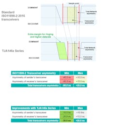
Both 2- and 5-Mb/s CAN FD communication have been added as optional extensions to the ISO11898-2 specification. This includes three timing requirements with regard to the bus and RxD bit width and the resulting receiver timing symmetry. Current CAN FD transceivers need to specify the ISO timing parameters as minimum.
Because it uses a highly accurate transmitter, CAN SIC is able to significantly increase the timing symmetry of the transceiver, as defined in the CiA601-4 specification. These parameters exceed the ISO11898-2 timing requirements and enable the data rate to push up to 8 Mb/s (Fig. 4, again).
The improved timing parameters of CAN SIC have been fully validated and are included in the CiA 601-4 as well as in NXP's CAN SIC datasheets. As a result, we can rate the technology up to 8 Mb/s. We can do so because we specify and guarantee the prescribed timing requirements under all operating conditions.
Does CAN SIC use the same cabling and connectors as CAN HS/FD?
Yes. The cabling and connectors are interchangeable even between CAN FD and CAN SIC. Additionally, CAN SIC offers potential benefit for the OEM or network owner by enabling cost saving on the network, either by using cheaper cables or enabling more efficient network topologies. Lower-quality cables can decrease signal quality and add further ringing. As CAN SIC decreases the effects of ringing in general, you can allow for lower-quality cables, thus saving cost.
Today’s CAN FD networks are limited to linear topologies to achieve a higher data rate. A cost-efficient way of routing a linear network is to connect nodes to each other and the bus by piggybacking (Fig. 1, again). This means a single connector is used for the incoming and outgoing cable, also called double cable crimping.
Double crimping adds additional strain to the cable and connector, making it more susceptible to failure and less reliable. The introduction of CAN SIC enables star-based networks at higher data rates, eliminating the need for double crimping. As a result, networks become more efficient in cabling. It also increases robustness and safety.
About the Author

William G. Wong
Senior Content Director - Electronic Design and Microwaves & RF
I am Editor of Electronic Design focusing on embedded, software, and systems. As Senior Content Director, I also manage Microwaves & RF and I work with a great team of editors to provide engineers, programmers, developers and technical managers with interesting and useful articles and videos on a regular basis. Check out our free newsletters to see the latest content.
You can send press releases for new products for possible coverage on the website. I am also interested in receiving contributed articles for publishing on our website. Use our template and send to me along with a signed release form.
Check out my blog, AltEmbedded on Electronic Design, as well as his latest articles on this site that are listed below.
You can visit my social media via these links:
- AltEmbedded on Electronic Design
- Bill Wong on Facebook
- @AltEmbedded on Twitter
- Bill Wong on LinkedIn
I earned a Bachelor of Electrical Engineering at the Georgia Institute of Technology and a Masters in Computer Science from Rutgers University. I still do a bit of programming using everything from C and C++ to Rust and Ada/SPARK. I do a bit of PHP programming for Drupal websites. I have posted a few Drupal modules.
I still get a hand on software and electronic hardware. Some of this can be found on our Kit Close-Up video series. You can also see me on many of our TechXchange Talk videos. I am interested in a range of projects from robotics to artificial intelligence.
Comment About the Article
To join the conversation, and become an exclusive member of Electronic Design, create an account today!

Leaders relevant to this article: