Synchronous Step-Down Switcher IC Supports Automotive Applications
The LT8645S from Linear Technology, now part of Analog Devices, was developed with an eye on the requirements for a step-down regulator intended for automotive applications, although it does fit other applications. For automotive power applications the LT8645S step-down switcher IC provides the basic functional requirements:
- Operation from 3.4V to 65V inputs to work with existing battery types and survive cold- crank transients.
- Ultra-low EMI to prevent noise from affecting internal and external electronic systems.
- High continuous output current to supply necessary power to associated circuits
- High efficiency switching to minimize battery drain
- Ultra-low quiescent current to consume minimum power when system loads are inactive
- Small, compact, thermally-efficient footprint to minimize p.c. board space and eliminate the need for forced air cooling.
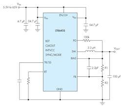
The LT8645S is a constant frequency, current mode synchronous step-down switching regulator that can provide up to 8A continuous output while safely operating with a 65V input. Its internal synchronous rectifier employs two power MOSFET switches that can provide outputs as low as 0.97V. The Figure 1is a step-down converter circuit using the LT8645S.
The LT8645S’s unique design maintains a minimum dropout voltage of only 60mV (at1A) under all conditions, enabling it to excel in scenarios such as automotive cold-crank. Furthermore, a fast minimum on-time of only 40ns enables 2MHz constant frequency switching from a 24V input to a 2.0V output, enabling designers to optimize efficiency while avoiding critical noise-sensitive frequency bands. The LT8645S’s 32-lead, 4mm x 6mm, thermally-enhanced LQFN package and high switching frequency allows small external inductors and capacitors, while providing a compact, thermally efficient footprint.
Based on Linear Technology’s Silent Switcher 2 architecture, the LT8645S employs two internal input capacitors as well as internal BST and INTVCC capacitors to minimize any hot loops. The INTVCC pin is the (~3.4V) output of an internal regulator that powers drivers and control circuits with maximum output of 25mA. The BST pin provides a drive voltage, higher than the input voltage, to the top synchronous rectifier power switch. This IC combines well-controlled switching edges and internal construction with an integral ground plane and the use of copper pillars in lieu of bond wires. This dramatically reduces EMI, is not sensitive to board layout, simplifies design and reduces emissions risk even when using two-layer p.c. boards. The LT8645S can pass the automotive CISPR25, Class 5 peak EMI limits with a 2MHz switching frequency over its entire load range.
Spread Spectrum
Spread spectrum frequency modulation is an option for lowering EMI even further. Spread spectrum mode varies the clock with a triangular frequency modulation of +20%. For example, if the LT8645S’s frequency is programmed to switch at 2MHz, spread spectrum mode modulates the oscillator between 2MHz and 2.4MHz. Tie the SYNC/MODE pin to INTVCC or an external supply of 3V to 4V to enable spread spectrum modulation, which operates only in the pulse skipping mode.
For optimal performance, use multiple VIN bypass capacitors, as shown in Figure 1. There are three VIN pins on the left side three on the right side of the package. Place 0.47μF capacitors as close as possible to the VIN pins, one on the left side and one on the right side. Place a third capacitor, 4.7μF or higher, on the VIN pin where the 5.5V to 65V input is applied.
The LT8645S’s Burst Mode operation exhibits only 2.5µA of quiescent current, which is well-suited for applications that include automotive/transportation always-on systems that extend battery life. Between bursts, all circuitry associated with controlling the output switch is shut down, reducing the input supply current to 1.7μA. Low ripple Burst Mode operation maintains high efficiency at low output currents while keeping output ripple below 10mVP-P. Applying a clock to the SYNC/MODE pin synchronizes the LT8645S to an external clock frequency and also causes pulse-skipping mode operation.
Pulse-skipping mode offers two major differences from Burst Mode. First, the clock stays awake at all times and all switching cycles are aligned to the clock. In this mode much of the internal circuitry is awake at all times, increasing quiescent current to several hundred μA. Second, it reaches full switching frequency at lower output load than in Burst Mode. To enable pulse-skipping mode, float the SYNC/MODE pin. Leakage current in this pin should be <1μA.
Special design techniques and a new high speed process enable high efficiency over a wide input voltage range, and the LT8645’s current mode topology enables fast transient response and excellent loop stability. Other features include internal compensation, power good (PG), soft-start/tracking and thermal protection.
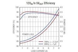
Synchronous rectification delivers efficiency as high as 94% with a switching frequency of 2MHz. Figure 2 is a plot of efficiency, as well as power loss when using two different switching frequencies and two different inductors.
Power Good
The open-drain PG pin is tied to VOUT with an external resistor. It goes high (true) when the LT8645S’s output voltage is within the ±8% window of the regulation point. Otherwise, the internal pull-down device will pull the PG pin low (false). To prevent glitches, both the upper and lower thresholds include 0.4% of hysteresis. PG is valid when VIN is above 3.4V. The PG pin is also actively pulled low during fault conditions, such as the EN/UV pin is below 1V, INTVCC has fallen too low, VIN is too low, or thermal shutdown.
The LT8645S will tolerate a short duration shorted output. To protect during output short-circuit and brownout conditions, the switching frequency folds back during the time the output is lower than the point necessary to maintain inductor current control. Synchronous output employs a top and bottom power MOSFET switches. The bottom switch current is monitored; if inductor current exceeds safe levels, the top switch will delay its switching until the inductor current falls to safe levels.
The LT8645S uses a constant frequency PWM architecture that you can program to switch from 200kHz to 2.2MHz by using a resistor from the RT pin to ground. Selection of the operating frequency is a trade-off between efficiency, component size, and input voltage range. High frequency operation allows use of smaller inductor and capacitor values, but also lowers efficiency and forces a smaller input voltage range.
You can program the output voltage with a resistor divider between VOUT and the FB pin. Referring to Figure 1, use the following formula to choose the resistors.
Use 1% resistors to maintain output voltage accuracy. If you need low input quiescent current and good light-load efficiency, use large resistor values for the FB resistor divider. Because the current flowing in the divider acts as a load current, it will increase the converter’s no-load input current. When you use large FB resistors, insert a 1pF to 10pF phase-lead capacitor between VOUT and the FB pin.
Layout
Large, switched currents flow in the LT8645S VIN and GND pins and the input capacitors. Loops formed by the input capacitors should be as small as possible by placing the capacitors adjacent to the VIN and GND pins. Because they exhibit low parasitic inductance use small case size capacitors such as 0603 or 0805.
Place input capacitors, along with the inductor and output capacitors on the same side of the circuit board, making their connections on that layer. Also, place a local, unbroken ground plane under the application circuit on the layer closest to the surface layer. The SW and BST nodes should be as small as possible. Keep the FB and RT nodes small so that ground traces can shield them from the SW and BST nodes.
Take care at higher ambient temperatures that the PCB layout ensures good IC heat sinking. Ground pins on the bottom of the package should be soldered to a ground plane. This ground should be tied to large copper layers below with thermal vias; these layers will spread heat dissipated by the LT8645S. Additional vias can reduce thermal resistance further. The maximum load current should be derated as the ambient temperature approaches the maximum junction rating.
Internal over-temperature protection monitors the junction temperature of the LT8645S. If the junction temperature reaches approximately 180°C, the LT8645S will stop switching and indicate a fault condition until the temperature drops about 10°C cooler.
Installing an external capacitor on TR/SS enables soft starting that prevents current surges on the input supply. During the soft-start ramp the output voltage will proportionally track the TR/SS pin voltage. For output tracking applications, TR/SS can be externally driven by another voltage source.
The TR/SS pin may be left floating if the function is not needed. An active pull-down circuit is connected to the TR/SS pin which will discharge the external soft-start capacitor in the case of fault conditions and restart the ramp when faults are cleared.
There are two versions of the LT8645S. The LT8645SEV grade is guaranteed by testing for 0 to 125°C, although performance is assured for -40 to 125°C by design and process monitoring. The LT8645SIV’s performance is guaranteed by testing for -40 to 125°C. Basically, the “IV” grade involves more testing than the “EV” grade.
About the Author

Sam Davis Blog
Editor-In-Chief - Power Electronics
Sam Davis was the editor-in-chief of Power Electronics Technology magazine and website that is now part of Electronic Design. He has 18 years experience in electronic engineering design and management, six years in public relations and 25 years as a trade press editor. He holds a BSEE from Case-Western Reserve University, and did graduate work at the same school and UCLA. Sam was the editor for PCIM, the predecessor to Power Electronics Technology, from 1984 to 2004. His engineering experience includes circuit and system design for Litton Systems, Bunker-Ramo, Rocketdyne, and Clevite Corporation.. Design tasks included analog circuits, display systems, power supplies, underwater ordnance systems, and test systems. He also served as a program manager for a Litton Systems Navy program.
Sam is the author of Computer Data Displays, a book published by Prentice-Hall in the U.S. and Japan in 1969. He is also a recipient of the Jesse Neal Award for trade press editorial excellence, and has one patent for naval ship construction that simplifies electronic system integration.


