Loss of Battery-Cable Isolation Prompts EV/HEVs to Protect Against Potential Hazards
The main function of an isolation monitor is to warn the EV/HEV operator that there is a potential (latent) hazardous condition. In the case of a single fault, this monitor is intended to protect the service/maintenance personnel and first responders, rather than the regular operators. However, if an external charger is connected to the EV/HEV, the situation may change. Now, the whole chassis may become energized if the system is faulty and has significant leakage. In the case of a symmetrical fault, where both the positive and negative isolation paths are compromised, it may lead to a short, causing fuses to blow. This would mean immediate loss of power—including loss of braking power—a situation that could cause accidents. In either case, when there is no proper isolation between battery cable and the chassis, the isolation monitor notifies the vehicle’s host computer to take corrective action.
In a typical topology of the modern electric vehicles and of the so-called IT (“Isolated Terra”) power systems, the whole Energy Storage System (ESS) or Rechargeable Energy Storage System (RESS) floats with respect to chassis (or ground). There are two main reasons for it:
1. Even a hard short (single-fault) from anywhere within the system to ground will not immediately produce a catastrophic event, or even a malfunction with respect to the continuous usability of the system.
2. A floating system actually enables the detection and measurement of leakages in the system.
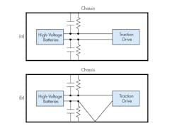
Figure 1 shows a typical floating system of a high-voltage battery powering the traction motor in an EV/HEV. Figure 1a is a safe system. Figure 1b shows a battery cable shorted to the chassis.
In operation, EV/HEV battery cable insulation may deteriorate either gradually or suddenly, shorting the battery voltage to the chassis. In addition, capacitances from the power system to the chassis may inadvertently change, accumulating hazardous charges. If either condition is detected, the operator should be notified to immediately service the vehicle. Another possibility is that the isolation of the car battery may be compromised during an accident or emergency so first responders may not be aware of a potential lethal voltage if they touch the terminals of the battery.
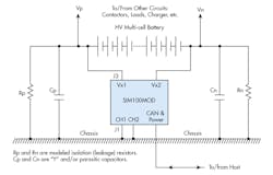
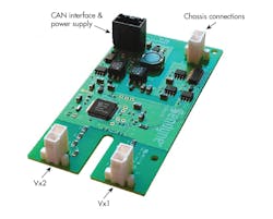
For protection purposes, today’s state-of-the-art technology only detects resistive leakages and only when the system voltage does not vary significantly. For industrial and commercial systems that would have to be in operation most of the time, that limitation can be dangerous. In contrast, Sendyne’s SIM100 is an automotive-rated isolation monitoring IC that detects potential electrical hazards during the dynamic operation of high voltage ungrounded systems, such as EVs and HEVs (Fig. 2). The SIM100MOD module (using the SIM100) is the first device of its kind capable of unambiguously detecting the electrical isolation state of a high-voltage system while the system is active and operating, and experiencing large voltage variations (Fig. 3). In addition, the SIM100MOD detects both resistive leakages and capacitively stored energy that could be harmful to vehicle operators.
Referring to Fig. 2, resistances Rp and Rn represent the resistive leakage between the battery terminals and chassis. They are Thévenin-equivalent of all possible multiple leakage sources, originating anywhere between and including the negative and positive terminals of the battery.
Chassis connections CH1 and CH2 provide a reference point for isolation measurements. The SIM100 continuously monitors continuity between these two connections to ensure the chassis is connected to the module. These two lines must have independent connections to chassis; they cannot be connected to a single stud that may separate from chassis but still keep these two lines joined; a separate stud or connector should be used for each of these two lines (CH1 and CH2). If these two lines to the chassis are not properly connected, or the amplitude of the built-in excitation source differs from the allowed value, then the SIM100 will report a Hardware Error.
Capacitances Cp and Cn represent the ever-present “Y” EMI suppression capacitors and also include any parasitics in the system. It is not likely that a significant capacitance is present that is connected not at the ends of the battery. However, at the load supplied by the battery, it is possible, and even probable, that some capacitance is present and may even be connected to some ac node of the drivetrain inverter or motor (again, either intentional or parasitic).
In any system, the battery will probably be naturally biased in such a way that the positive terminal will be more positive than chassis, and negative terminal more negative, unless an external charger or some other apparatus are connected, in which case any biasing scenarios are possible; the point being that sensing of the voltage in respect to chassis must be capable of bipolar operations. The particular value if this Ohms/volt isolation resistance actually corresponds to a specific maximum fault current.
Complicating the measurement problem is that the voltage of the battery changes when it releases or accepts energy, where volts or even tens of volts variations are typical. With the SIM100, battery voltage variations are treated as useful test signals rather than noise, enabling more precise measurements. In particular, this refers to separate estimates for the modeled isolation resistances and capacitances at the bottom (negative) and top (positive) sides of the battery. Such separate estimates are not possible with the use of just the excitation source signals.
The SIM100 looks at the whole network of constituent elements: battery, leakage resistors, capacitors, and specifically including its own internal circuit—similar to what one would see if simulating the whole circuit in SPICE. Then, using mathematical and statistical methods, the internal state of the system (i.e., the assumed-constantly-changing values of all components) is calculated.
The SIM100MOD continuously monitors the isolation resistance between a vehicle’s power system and chassis for deterioration of insulation and potentially dangerous leakage current. The module detects not only resistive leakages, but also capacitively stored energy that could be harmful to human operators. The SIM100MOD can detect these potential hazards while the system is operating and voltages are fluctuating as much as 100 V.
Sendyne employs a proprietary, patent-pending advanced algorithm that detects all sources of leakage, including multiple, simultaneous symmetrical and asymmetrical faults as well as resistive paths between the chassis and points in the battery with the same potential as the chassis. In the case of an insulation fault, the unit identifies the position of the fault relative to the battery terminals.
· Operations performed by the SIM100MOD include:
· Measuring voltage from each battery terminal to the chassis.
· Measuring and reporting modeled leakage resistances per model adapted by the safety standards ISO6469-1, FMVSS §571.305 and others.
· Reporting calculated isolation resistance in Ω/V per requirements of the safety standards.
· Measuring and reporting the value of capacitance from each battery terminal to chassis.
· Calculating and reporting the energy stored by the total capacitance between the battery and chassis.
· Continuously monitoring connections of the voltage sense lines to the battery terminals and reporting inadequate connections.
· Continuously monitoring the connection of the unit to chassis and reporting inadequate connections.
· Providing high immunity to common-mode noise that can be present on the battery terminals.
· Storing the value of the maximum design voltage of the battery used in calculations of the isolation resistance and stored energy (nonvolatile). If the actual observed battery voltage is higher than the set maximum voltage, the higher value is used in the calculations of the isolation resistance and stored energy.
· Storing the calibration of the voltage measurements and other parameters; all reported measurements have their respective calibration parameters applied automatically (nonvolatile).
· Providing a built-in galvanically isolated and intrinsically leakage-safe excitation source.
· Measuring the internal isolated power supply voltage for system diagnostics.
· Measuring the module’s temperature for system diagnostics.
Communications are achieved with the host ECU via an isolated CAN 2.0B interface (500 kbit/s). The SIM100MOD module has a power supply input voltage of 5 V to 53 V, thereby accommodating most vehicle systems. It operates over of -40°C to +105°C temperature range. The module was designed to meet ISO 6469-3:2011-12 /FMVSS 305.
Sendyne achieved this performance by utilizing its proprietary, patent pending modeling and embedded scientific computing technology. The SIM100 IC, the brains of the system, models the supervised ungrounded system, and through stochastic optimization methods, determines the condition of all types of electrical paths from the high voltage system to the chassis. SIM100 ICs are pre-programmed and do not require additional firmware.
An evaluation kit, with cables, CAN to USB dongle and software is available. Sendyne’s SIM100 IC is also obtainable, with minimum quantity orders.
About the Author

Sam Davis Blog
Editor-In-Chief - Power Electronics
Sam Davis was the editor-in-chief of Power Electronics Technology magazine and website that is now part of Electronic Design. He has 18 years experience in electronic engineering design and management, six years in public relations and 25 years as a trade press editor. He holds a BSEE from Case-Western Reserve University, and did graduate work at the same school and UCLA. Sam was the editor for PCIM, the predecessor to Power Electronics Technology, from 1984 to 2004. His engineering experience includes circuit and system design for Litton Systems, Bunker-Ramo, Rocketdyne, and Clevite Corporation.. Design tasks included analog circuits, display systems, power supplies, underwater ordnance systems, and test systems. He also served as a program manager for a Litton Systems Navy program.
Sam is the author of Computer Data Displays, a book published by Prentice-Hall in the U.S. and Japan in 1969. He is also a recipient of the Jesse Neal Award for trade press editorial excellence, and has one patent for naval ship construction that simplifies electronic system integration.


