Fast Charging: An Attractive Option for EV Owners with Range Anxiety
We all have seen electric cars on the street. They look very futuristic and demand a second glance from passersby. As far as convenience, they can be driven in the carpool lane, parked, and even charged for free in some places. Their price tag is still an impediment to their large adoption by consumers, even if incentives exist in many countries.
Another reason for their slow expansion is the rather low drive range these vehicles offer. The longest range available on the market is 300 km (a little over 186 miles) in real driving conditions. Although this would be sufficient for the usual daily commute from home to office, people have the feeling this is not enough for the few times a year they’ve got to drive 500 km (over 310 miles). This is known as range anxiety, or the fear of being short of gas (or electricity in this case). So that’s 300 km you can do before you have got to spend several hours at the charging station to continue on your journey. Fortunately, there is a solution to reduce your entertainment bill at the service; it is fast charging. If we could charge our EV to full capacity in the same time as we fill our gasoline tanks, range anxiety would not be such a problem.
Firstly, what problems does fast charging cause? Well, to cut to the chase, fast charging can be harmful to the battery cell. In order to fast charge, we need high current. The higher the current, the higher the cell temperature will be, which affects the calendar life of the cell. Also at high current, a reaction at the Solid Electrolyte Interface of the negative electrode occurs. This reaction forms metal lithium dendrites and it is amplified at low temperatures (sub 0oC). These dendrites can cause great damage to the cell and even the car itself. Indeed, if one of these dendrites goes sufficiently long, it can reach out to the positive electrode and generate an internal short circuit, which, if not controlled properly, could set your car on fire. This is not an ideal scenario.
So we need to control the charge operation condition and be able to design a battery cell that could accept a high current.
Let’s have a look at a very common cell that can be found in laptops and Teslas, a cylindrical Li-ion cell of format 18650. The cell is an NCA/graphite chemistry and has a capacity of 2.8Ah, which is a high-energy cell for this format. The cell is fully digitized in BDS, all geometrical details are input, and a high-fidelity physics-based model is configured. The charging test can begin.
With Battery Design Studio engineering simulation software, you can test the cell at three different charging constant currents, 3A, 6A, and 9A, and at four different ambient temperatures -10oC, -5oC, 5oC, and 25oC. These temperatures represent very common ambient temperatures at which we operate our vehicles.
In order to see the point at which lithium deposits, BDS has an easy monitor, which looks at the negative potential near the separator. If it goes negative, this indicates you may deposit lithium. Therefore, the challenge is to have high current charge without approaching the zone where the negative electrode potential goes negative.
The results show that there is actually one condition where lithium deposition occurs, at 3A charge, this is during the -10oC test.
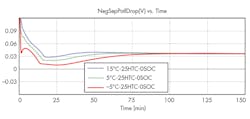
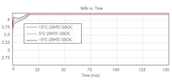
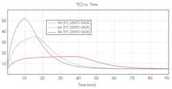
At 6A and 9A, no deposition, whatever the test ambient temperature as illustrated in Fig. 1 for the 9A charges. Figure 2 shows the cell voltage evolution at 9A during the -5 oC, 5 oC, and 15oC tests, highlighting the cell heat up at -5 oC, where the voltage shows a local max around 2 min. However, the temperature levels reached during this high-current charge are too high, above 60oC in the case of the 9A charge test. As shown in Fig. 3, this could lead to safety issues.
1. Negative potential drop near separator for different temperatures at 9A charge.
2. Cell voltage evolution at 9A charge for different temperatures.
3. Temperature evolution for 3A, 6A, and 9A charge.
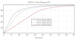
Looking at how much state of charge (SOC) we can charge to in 20 minutes, which we would agree is acceptable for a service stop, we note in Fig. 4 that at 9A, 80% of the cell can be charged, which is really satisfying, but the temperature is way too high. To be safe, Fig. 3 shows we should have stopped the charge when the cell temperature reached 45oC. At this temperature level, the SOC is barely ~55%. Not enough to complete your 500 km journey!
4. SOC evolution for 3A, 6A, and 9A charge.
So the charging rate is limited by allowable temperature rise of the cell. This temperature rise is actually due to the high positive and negative activation over potential, but also by the diffusion and ohmic polarization in electrolyte, which we can analyze in BDS as shown in Fig. 5.
5. Different voltage loss sources at 9A charge.
How can we improve this fast charge in 20 minutes?
First, we need to find a way to reduce the impact of the activation overpotential by increasing the surface area of active material. To reduce the electrolyte diffusion, we have to increase the porosity and reduce the tortuosity of the electrodes and the separator. Finally, the tabs and the current collectors are also sources for heat, and their geometry can be adjusted to generate less ohmic heat.
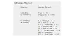
We are facing a complex problem, with a lot of parameters to control. In addition, we would like to find out how we should variate the cell design so we can charge the cell in 20 minutes. Of course, we should ensure the temperature of the cell doesn’t rise above a certain safety threshold (45oC) and no lithium gets deposited, obviously.
By coupling BDS to HEEDS, Siemens’ design exploration tool, we can perform this complex design change automatically. So we have the following problem as explained in Fig. 6:
6. Design exploration problem.
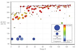
We ran the study and HEEDS converged to an improved design after ~160 designs.
7. Evolution of max charge capacity for each design.
There was a 20% improvement in the performance of the charging capacity over 20 minutes, as shown in Fig. 7.
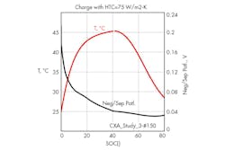
8. Evolution of the cell temperature and negative potential drop near separator as a function of SOC.
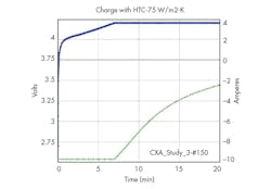
9. Cell voltage and applied current evolutions as a function of time.
Looking at the results for the best design, no lithium gets deposited as shown in Fig. 8, so there is no danger on this side. The limiting factor is the cell temperature, which reaches 45oC as illustrated in Fig. 8. The cell voltage evolution is shown in Fig. 9.
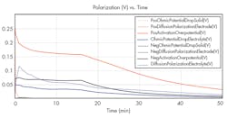
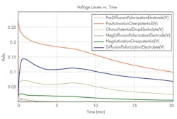
10. Voltage losses for best design.
The heat from the positive activation overpotential and electrolyte voltage losses are the biggest contributors to the overall cell heat-up.
Nevertheless, as illustrated in Fig. 10, we have been able to modify the cell voltage losses to limit the heat-up and allow its charge to rise to 81% SOC in 20 minutes in safe conditions.
