80-V Multiphase Slave Controller Simplifies Battery-Backup Power Conversion
The LT8708-1 developed by Analog Devices is a 98% efficient bidirectional regulator controller IC that operates as a slave to a master LT8708 IC. One or more slaves can be connected to a single master, proportionally increasing power and current capability of the system. The LT8708-1 slave can deliver as much current or power as the master.
This controller operates with a single inductor over a 2.8- to 80-V input voltage range and can produce an output voltage from 1.3 to 80 V, delivering up to several kilowatts, depending on the choice of external components and number of phases. Characteristics of the LT8708-1 include:
- Synchronous rectification
- Single inductor
- Allows VIN above, below, or equal to VOUT
- Six independent forms of regulation: VIN current (forward and reverse); VOUT current (forward and reverse); VIN and VOUT
- Forward and reverse discontinuous conduction mode (DCM) supported
- Supports MODE and DIR pin changes while switching
Available in a 5- × 8-mm QFN-40 package, the LT8708-1 has three temperature grades, with operation from –40 to 125°C for the extended and industrial grades and a high temperature automotive range of –40 to 150°C.
As the master of the multiphase system, the LT8708 and its respective error amplifiers determine the current necessary to regulate VIN, VOUT, VIN current, and VOUT current. The master LT8708 controls regulation voltages and current limits for the system. The slave LT8708-1 operates by sensing the IOUT(MASTER) and delivers a proportional amount of. IOUT(SLAVE) that’s proportional to IOUT(MASTER).
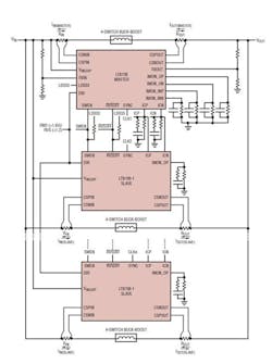
1. Here’s a simplified diagram of the multiphase configuration.
The master and slave VIN current are referred to as IIN(MASTER) and IIN(SLAVE), respectively. Figure 1 shows a simplified drawing of a multiphase system with one LT8708 and multiple LT8708-1s. It illustrates the basic connections needed to add LT8708-1s to a multiphase system.
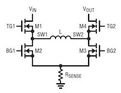
The LT8708-1 employs the same power switch control as the LT8708. Figure 2 shows a simplified diagram of how the four power switches are connected to the inductor, VIN, VOUT, and ground.
2. Shown is the 4-switch buck-boost circuit in Figure 1.
Adding Phases
The LT8708 master controls the VIN and VOUT regulation voltages through its FBIN and FBOUT pins. The slaves primarily duplicate the master’s IOUT(MASTER) current, so the slave’s FBIN and FBOUT pins and related circuitry typically aren’t used.
The master LT8708’s current regulation pins (IMON_INP, IMON_INN, IMON_OP, IMON_ON) monitor and limit the per-phase VIN current and VOUT current. The LT8708-1 complies with these limits by proportionally regulating the IOUT(SLAVE). The slave’s IMON pins are typically used differently than on the LT8708.
You can use VINHIMON and VOUTLOMON pins to set up VIN overvoltage and VOUT undervoltage lockouts on both the LT8708 and the LT8708-1. Typically, however, divider networks are only necessary on the master LT8708, since activation of the VINHIMON or VOUTLOMON comparator, on any phase, is communicated to all phases through the shared RVSOFF pin connection. Utilizing the VINHIMON and VOUTLOMON pins on additional phases offers redundancy for those functions.
Soft-Start
A soft-start (SS) sequence happens independently and in parallel for each phase. That’s because each phase has its own SS pin, external capacitor, and related circuitry. In the INITIALIZE state, the SS pin is pulled low to prepare for soft-starting the switching regulator. Also, VC is forced to command near zero current, and IMON_OP is forced to ~1.209 V (typical) to improve the transient behavior when the LT8708-1 subsequently starts switching.
After SS has been discharged to less than 50 mV, the SOFT-START 1 state begins. In this state, an integrated 180-kΩ (typical) resistor from 3.3 V pulls SS up. The rising ramp rate of the SS pin voltage is set by this 180-kΩ resistor and the external capacitor connected to this pin.
After SS reaches 0.2 V (typical), the LT8708-1’s integrated pull-up resistor is reduced from 180 kΩ to 90 kΩ to increase the rising ramp rate of the SS pin voltage. This ensures that the slave chip enters the normal mode before the master chip, preventing saturation of the regulation loop during startup.
Switching remains disabled until either ICP or ICN voltage becomes higher than 510 mV (typical) (SOFT-START 3), or SS reaches 0.8 V (typical) (SOFT-START 2). As soon as switching is enabled, VC is free to slew under the control of the internal error amplifiers. This allows the average IOUT(SLAVE) to quickly follow the average IOUT(MASTER) without saturating the slave’s regulation loop. During soft-start, the LT8708-1 employs the same switch control mechanism as the LT8708.
When SS reaches 1.8 V (typical), the LT8708-1 exits soft-start and enters normal mode. Typical values for the external soft-start capacitor range from 220 nF to 2 μF. It’s recommended to use the same brand and value SS capacitor for all of the synchronized LT8708/ LT8708-1(s). Using a slave SS capacitor value significantly higher than the master SS capacitor value can result in undesirable startup behavior.
Control Overview
The LT8708-1 is a slave current-mode controller that regulates the average IOUT(SLAVE) based on the master’s ICP and ICN voltages, or equivalently, the average IOUT(MASTER). In a simple example of IOUT(SLAVE) regulation, the CSPOUT–CSNOUT pins receive the IOUT(SLAVE) feedback signal, which is summed with the ICP and ICN signals from the LT8708 to generate the IMON_OP voltage. The IMON_OP voltage is compared to an internal reference voltage.
Low IMON_OP voltages raise VC, which causes IOUT(SLAVE) to become more positive (or less negative) and increases the current out of the IMON_OP pin. Conversely, higher IMON_OP voltages reduce VC, which causes IOUT(SLAVE) to become less positive (or more negative) and reduces the current flowing out of the IMON_OP pin.
VC is the combined output of five internal error amplifiers and typically has a min to max range of about 1.2 V. The maximum VC voltage commands the most positive inductor current, and thus commands the most power flow from VIN to VOUT. The minimum VC voltage commands the most negative inductor current, and as result commands the most power flow from VOUT to VIN.
Conduction Modes
As with the LT8708, the LT8708-1 has one bidirectional and three unidirectional current conduction modes (CCM, HCM, DCM, and Burst Mode operation, respectively). The
LT8708-1’s MODE, DIR, and RVSOFF pins operate in the same way as in the LT8708 to select the desired conduction modes. Generally, keep all phases of an LT8708 system in the same conduction mode. This is done by setting all MODE and DIR pins to the same states, or by shorting all MODE pins together and all DIR pins together. In addition, the RVSOFF pins of all phases should be connected together.
When operating in the forward hybrid conduction mode (FHCM), the LT8708-1 operation differs slightly from the LT8708. Instead of measuring the ICN pin voltage for light load detection, the LT8708-1 measures the IMON_ON pin. Light load is detected when IMON_ON is above 245 mV (typical). Therefore, FHCM operation requires a 17.4-kΩ resistor, and a parallel filter capacitor, from ground to the IMON_ ON pin of the LT8708-1. Reverse hybrid conduction mode (RHCM) operates identically in the LT8708 and LT8708-1.
EV Power Management
The LT8708/-1 buck-boost switching regulator controller can operate between two batteries that have the same voltage, which is ideal for redundancy in self-driving cars. Advanced driver-assistance systems (ADAS) in autonomous electric-vehicle (EV) applications employ two low-voltage batteries like a 12-V sealed lead-acid or a 12-V Li-ion for redundancy requirements. Two batteries are used for redundancy, and in some cases for higher power—more than a single battery can supply.
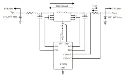
Figure 3 shows a simplified diagram of the LT8708/-1 operating from an input voltage that can be above, below, or equal to the output voltage, making it well-suited for two each 12-, 24- or 48-V batteries commonly found in electric and hybrid vehicles. It operates between two batteries and prevents system shutdown should one of the batteries fail. The LT8708/-1 can also be used in 48-V/12-V and 48-V/24-V dual-battery systems.
3. This is a simplified diagram of the LT8708’s bidirectional operation.
Another application is for an input voltage to power a load, where this same input voltage is used to power a LT8708/-1 circuit that charges a battery or bank of supercapacitors. When the input voltage goes away, the load maintains power without disruption from the battery or supercapacitors by way of the LT8708’s bidirectional capability.
Using four resistors, you can monitor and limit forward and reverse current for the input and output sides of the converter. You can set all four current limits (forward input, reverse input, forward output, and reverse output) independently. In combination with the DIR (direction) pin, the chip can be configured to process power from VIN to VOUT or from VOUT to VIN, which is ideal for automotive, solar, telecom, and battery-powered systems.
About the Author

Sam Davis
Sam Davis was the editor-in-chief of Power Electronics Technology magazine and website that is now part of Electronic Design. He has 18 years experience in electronic engineering design and management, six years in public relations and 25 years as a trade press editor. He holds a BSEE from Case-Western Reserve University, and did graduate work at the same school and UCLA. Sam was the editor for PCIM, the predecessor to Power Electronics Technology, from 1984 to 2004. His engineering experience includes circuit and system design for Litton Systems, Bunker-Ramo, Rocketdyne, and Clevite Corporation.. Design tasks included analog circuits, display systems, power supplies, underwater ordnance systems, and test systems. He also served as a program manager for a Litton Systems Navy program.
Sam is the author of Computer Data Displays, a book published by Prentice-Hall in the U.S. and Japan in 1969. He is also a recipient of the Jesse Neal Award for trade press editorial excellence, and has one patent for naval ship construction that simplifies electronic system integration.
You can also check out his Power Electronics blog.


