New Motor Designs Help EV Makers Kick the Rare-Earth Habit (Part 2)
Members can download this article in PDF format.
What you’ll learn:
- How the switched reluctance motor's (SRM) architecture eliminates the need for magnets and rotor windings.
- Why SRMs are some of the most rugged and cost-effective motor technologies available.
- A look at the strengths, weaknesses, and design challenges involved with using SRMs in EVs.
Electric vehicles (EVs) are still in their infancy with several "teething problems" that must be overcome before they can deliver on their potential to cut U.S. carbon emissions by as much as 24%.1 Among the most immediate issues is making EVs more affordable by developing motors that can be manufactured without any so-called rare-earth minerals. These include neodymium, terbium, and dysprosium used in the permanent-magnet synchronous motors (PMSMs) found in roughly 90% of the EVs on the road today.2
In Part 1 of this series, we explored several different types of wound-rotor synchronous motors (WRSMs) that replace the PMSM's permanent magnets with electromagnets. This installment will focus on switched reluctance motors (SRMs), one of the most common types of what’s referred to as induction machines. The concluding installment will explore synchronous reluctance motors (SynRMs), another promising sub-species of induction-type machines.
Switched Reluctance Motors 101
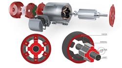
The SRM is a double salient-pole motor, which means that the magnetic field projects outwards from the stator and the rotor (Fig. 1). The rotor in an SRM doesn’t contain permanent magnets or windings while the stator is wound to produce the poles across the diameter of the motor.
An SRM’s rotor, unlike a traditional permanent-magnet motor, is constructed from a stack of ferroelectric material like laminated iron sheets that has "teeth" cut lengthwise around its circumference. The rotor is surrounded by a stator comprised of electromagnetically energized poles evenly distributed around the circumference.3
The rotor's teeth are magnetically permeable and the empty notches on either side of them are weakly permeable, forming "salient poles." These are areas of increased magnetic-flux density that allow the motor's drive circuitry to pull the rotor from one position to the next by sequentially switching power to consecutive stator windings/phases.
When the stator is electrically excited, the magnetic flux generated is always maximized over the smallest reluctance path, which happens through the ferroelectric material in the rotor pole. This results in magnetization of the rotor pole that rotates to come in alignment with the excited stator phase. This causes a further reduction in the reluctance due to the reduction of the air gap and further maximization of the flux.4
When Magnets Attract
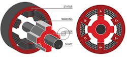
Unlike series DC machines or AC induction motors, the SRM operates solely on magnetic attraction. Thus, it becomes necessary to avoid a "lock-up" condition by having at least some of the rotor's poles offset from the stator's coils at all times. This is accomplished by constructing the rotor with a different number of teeth/poles than the stator, ensuring that when some of its poles are aligned with the stator electromagnets, others will be in between them.
Figure 2 shows a typical SRM design, usually referred to as a “6/4” configuration (six stator poles and four rotor poles). As we'll see shortly, other rotor/stator configurations with higher pole counts can also be used to improve the motor's operating characteristics.5
Since the currents induced in the rotor's teeth by the rotating magnetic field (RMF) cause the rotor to closely follow the stator's energized poles, an SR motor's rotational speed is controlled by varying the RMF's switching speed. The amount of torque produced by an SR motor is proportional to the amount of current put into its windings. In other words, its torque production is unaffected by motor speed. This is very different from AC induction-type motors in which the rotor tends to lag behind the stator's rotating field, a phenomenon that becomes more pronounced as the motor's rpm ramps up.
In addition to their excellent torque characteristics, SRMs are very economical to build. The rotor and its poles can be built up from stacked steel laminations, eliminating the need for rotor windings, rare-earth materials, or magnets. The lack of any type of conductor in the SRM rotor means that overall rotor losses are considerably lower than in other motors that use conductors in their rotors.
SRM Drawbacks
SRMs also have several disadvantages, many of which are due to their stator electromagnets having to be driven by a unipolar (DC) trapezoidal waveform that switches between 0 V and the desired drive voltage. This is very different than the bipolar (AC) drive waveforms used by most other motors that swing symmetrically around 0 V.
While the absence of an AC component almost eliminates the iron losses that occur in the rotors of most other types of motors, the trapezoidal wave's sharp transitions produce “torque ripple,” i.e., high-frequency variations in its output torque. The resulting mechanical pulses subject the rotor to high levels of potentially destructive tension and compression as well as producing large amounts of noise and vibration that would be unacceptable in an EV.
Fortunately, torque ripple can be reduced in several ways. For instance, the number of poles in the rotor and stator can be increased,5 albeit at the cost of greater manufacturing complexity and more expensive drive circuitry.
Driving SRMs
Speaking of drive circuitry, the waveforms used to drive SRMs place unique and much more demanding (and potentially expensive) requirements on the electronics used to produce the stator's trapezoidal drive pulses. For one thing, the stator drive current pulse must be ramped up and down quickly and be precisely timed to align with the rotor's position relative to the stator.
Achieving such precise timing requires the controller to have very accurate knowledge of the rotor position, typically supplied by a relatively expensive (and delicate) absolute position encoder. Recently, though, techniques have been developed to use less costly, more robust solutions, such as Hall-effect sensors.
In addition, the drive electronics must accommodate the stator's unusual current requirements, which vary in a complex relationship to the rotor pole's position. That’s because the inductance of the stator's electromagnets increases as a rotor/pole pair approaches alignment, making it much more difficult to increase the current when it's most needed for optimum torque production. (For a more thorough, easy to understand explanation of this phenomenon, read Texas Instruments' application note "Switched Reluctance Motor (SRM) Inverter Design With the DRV8343-Q1.”6)
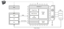
Generating the complex, time-sensitive waveforms needed to efficiently energize an SRM stator while simultaneously damping some of its torque ripple requires much more compute power than most MCUs could deliver, even a few years ago (Fig. 3).
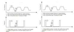
Fortunately, advances in MCU architecture, finer process geometries, and the increased integration of dedicated functional hardware cores (PWMs, array processors, ADCs, etc.) now make it possible for even mid-range controllers to perform the complex sensing and waveform generation necessary to support efficient SRM operation (Fig. 4).
A New Hope
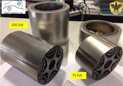
There’s another type of reluctance motor known as a synchronous reluctance motor (SynRM). It’s based on an advanced rotor structure constructed with tapered multilayer air gaps that shape the salience of each pole in relation to its proximity to the stator (Fig. 5).7
A SynRM motor offers many of the advantages of the SRM, plus a few of its own, including that it can be driven with a sinusoidal waveform. By eliminating the need for a trapezoidal drive pulse, SynRMs aren’t subject to the high levels of torque ripple produced by SRM machines. Part 3 of this series will be devoted to exploring this highly promising motor technology.
References
1. “Sources of Greenhouse Gas Emissions,” U.S. EPA.
2. Kevin Clemens, “Eliminating Rare Earth Elements in Electric Motors,” EE Power, August 18, 2022.
3. Han S, Diao K, Sun X, “Overview of multi-phase switched reluctance motor drives for electric vehicles,” Advances in Mechanical Engineering. 2021;13(9).
4. Lee Teschler, “What's the Difference Between Asynchronous and Synchronous Motors?,” Machine Design, January 4, 2013.
5. Adrea Credo, Giuseppe Fabri, Marco Villani , Mircea Popescu, “High speed synchronous reluctance motors for electric vehicles: a focus on rotor mechanical design,” 2019 IEEE International Electric Machines & Drives Conference (IEMDC).
6. Anuj Narain, “Switched Reluctance Motor (SRM) Inverter Design With the DRV8343-Q1,” Texas Instruments Document #SLVAEN9, January 2020.
7. Antti Lehikoinen, “Switched and Synchronous Reluctance Machines,” Smeklab, Motors and Magnetics Consulting, June 2023.
About the Author

Lee Goldberg
Contributing Editor
Lee Goldberg is a self-identified “Recovering Engineer,” Maker/Hacker, Green-Tech Maven, Aviator, Gadfly, and Geek Dad. He spent the first 18 years of his career helping design microprocessors, embedded systems, renewable energy applications, and the occasional interplanetary spacecraft. After trading his ‘scope and soldering iron for a keyboard and a second career as a tech journalist, he’s spent the next two decades at several print and online engineering publications.
Lee’s current focus is power electronics, especially the technologies involved with energy efficiency, energy management, and renewable energy. This dovetails with his coverage of sustainable technologies and various environmental and social issues within the engineering community that he began in 1996. Lee also covers 3D printers, open-source hardware, and other Maker/Hacker technologies.
Lee holds a BSEE in Electrical Engineering from Thomas Edison College, and participated in a colloquium on technology, society, and the environment at Goddard College’s Institute for Social Ecology. His book, “Green Electronics/Green Bottom Line - A Commonsense Guide To Environmentally Responsible Engineering and Management,” was published by Newnes Press.
Lee, his wife Catherine, and his daughter Anwyn currently reside in the outskirts of Princeton N.J., where they masquerade as a typical suburban family.
Lee also writes the regular PowerBites series.
Comment About the Article
To join the conversation, and become an exclusive member of Electronic Design, create an account today!

Leaders relevant to this article: