Bridge-Driver IC Supports Automotive Brushed DC Motors, Solenoids
Today’s automobiles have only a slight resemblance to those first horseless carriages introduced over 100 years ago. For example, those first personal transportation vehicles didn’t have any electric motors or even a battery (power for the spark ignitor came from a magneto, a low-efficiency generator). In contrast, today’s cars typically have at least 30 to 40 electric motors and often more—and that doesn’t include the traction motors of electric vehicles and hybrid EVs.
It’s easy to assume that nearly all of these motors are the brushless DC (BLDC) type, but the reality is that the classic brushed DC motor is still widely used due to its many performance, cost, and other desirable attributes. Interestingly, many of these considerations also apply to the linear-motion solenoid, another fundamental, widely used “mover.” It has many electrical and magnetic similarities to the brushed motor, despite the obvious differences.
Brushless motors and solenoids can be driven by a simple connection to a DC source via an on/off switch. However, that basic arrangement and associated performance doesn’t offer the motion control and flexibility provided by an advanced controller that’s required by modern architecture.
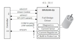
That’s where a sophisticated driver can help. Texas Instruments’ DRV8242-Q1 automotive-qualified H-bridge driver with integrated current sense and diagnostics addresses the need for better control and management of both brushed motors and solenoids in the harsh automotive environment. These drivers integrate an N-channel H-bridge, charge pump regulator, high-side current sensing with regulation, current proportional output, and protection circuitry (Fig. 1).
Features of the New Bridge Driver
Going well beyond a bare-bones driver, these devices offer voltage monitoring and load diagnostics as well as protection features against overcurrent and overtemperature, with fault conditions indicated on a package pin. A low-power sleep mode offers quiescent current of 1.3 µA.
Among the other attributes of these drivers, which are AEC-Q100-qualified for automotive applications (temperature grade 1: –40 to +125°C), are:
- 4.5- to 35-V operating range
- Support of 3.3- and 5-V logic inputs
- RON_LS + RON_HS = 250 mΩ in the QFN package
- Maximum IOUT = 6 A (QFN package)
- PWM frequency operation up to 25 kHz with automatic dead-time assertion
- Configurable slew rate and spread-spectrum clocking for low EMI.
- Integrated current sense, eliminating the need for a separate shunt resistor
- Proportional load-current output
- Configurable current regulation
- Numerous protection and diagnostic features with configurable fault reaction (either latched or retry), including load diagnostics in both the off-state and on-state to detect open load and short circuit; supply-voltage monitoring; overcurrent protection; and overtemperature protection
The devices come in three functional variants: hardwired interface: HW (H), and two SPI interface variants, namely SPI(P) and SPI(S), with SPI (P) for externally supplied logic supply and SPI (S) for internally generated logic supply. The SPI interface variants offer more flexibility in device configuration and fault observability.
The devices are offered in a 3.5- × 4.5-mm, 20-lead QFN package as well as other package options. The comprehensive 70-page datasheet includes full details on setup, waveforms, timing, and other critical design-in information.
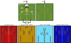
Although TI doesn’t have an evaluation module for these drivers, the datasheet shows a layout example for a 4 cm × 4 cm × 1.6 mm, 4-layer PCB for a leaded-package device, using 2-oz. copper on top and bottom signal layers and 1-oz. copper on internal supply layers (Fig. 2).
TI also has several useful application reports discussing motor-driver ratings and layout (see References).
References
Calculating Motor Driver Power Dissipation
About the Author

Bill Schweber
Contributing Editor
Bill Schweber is an electronics engineer who has written three textbooks on electronic communications systems, as well as hundreds of technical articles, opinion columns, and product features. In past roles, he worked as a technical website manager for multiple topic-specific sites for EE Times, as well as both the Executive Editor and Analog Editor at EDN.
At Analog Devices Inc., Bill was in marketing communications (public relations). As a result, he has been on both sides of the technical PR function, presenting company products, stories, and messages to the media and also as the recipient of these.
Prior to the MarCom role at Analog, Bill was associate editor of their respected technical journal and worked in their product marketing and applications engineering groups. Before those roles, he was at Instron Corp., doing hands-on analog- and power-circuit design and systems integration for materials-testing machine controls.
Bill has an MSEE (Univ. of Mass) and BSEE (Columbia Univ.), is a Registered Professional Engineer, and holds an Advanced Class amateur radio license. He has also planned, written, and presented online courses on a variety of engineering topics, including MOSFET basics, ADC selection, and driving LEDs.


