Radar and Ultrasonic Sensors Strengthen ADAS Object Detection
Download this article in PDF format.
According to the National Safety Council (NSC), as many as 40,000 people died in motor vehicle crashes in the U.S. in 2016, the highest total in more than a decade. Among the main causes were speeding, driving while impaired, and texting while driving. Including the 4.6 million people injured, the total costs from medical expenses, lost wages and productivity, and property damage could exceed $432 billion.
1. The moment when Nigel realized that his homemade parking-assist system had a coding error. (Source: NewsUK)
To help improve road safety and satisfy increasingly stringent government regulations, automakers are adding a range of diverse technologies to their new models that help drivers avoid accidents, both at high speeds and when backing up or parking. These systems can be grouped into the category of advanced driver-assistance systems (ADAS). In addition to increasing safety, ADAS applications improve comfort, convenience, and energy efficiency.
Typical ADAS features include blind-spot and lane-departure warning, forward collision and rear cross-traffic warning, automatic emergency breaking, lane-keep assist, and adaptive cruise control.
The Society of Automotive Engineers (SAE) has defined six levels of vehicle automation (Fig. 2). It spans from Level 0, which has no automation, to Level 5, which involves fully autonomous vehicles. As automation expands, driver assistance and ADAS play an increasingly important role.
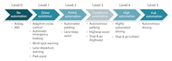
2. Object-detection systems are important parts of all automation levels other than Level 0. (Source: “TI’s smart sensors designed for automated driving applications” PDF, p. 3, Fig. 1)
The Role of Object Detection in ADAS
An automated driving system requires many functional blocks, including sensors that capture information about the surrounding environment, integrated circuits (ICs) for communication, high-performance microprocessors (MPUs) or digital-signal processors (DSPs) for sensor data analysis, and microcontrollers (MCUs) to activate and control mechanical functions.
The primary role of a sensor in the system is to detect objects such as vehicles, pedestrians, or stationary obstacles. Of course, an accident can happen at any time: The sensor system must operate over the whole performance envelope of the vehicle, both at highway speeds and in the parking garage,
Ultrasonics and radar are two complementary technologies that work together to achieve the desired result. Let’s review how they are used in ADAS applications.
Ultrasonic Sensing Fundamentals
As the name implies, an ultrasonic sensing system operates by transmitting short bursts of sound waves and measuring the time taken for the sound to travel to a target object, be reflected, and return to the receiver (Fig. 3). The distance to the object is a function of the travel time and the speed of sound in air, approximately 346 m/s.
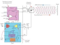
3. This ultrasonic system features a PGA450 analog front end. (Source: Author/PGA450-Q1 PDF)
Objects closer to the transmitter produce a stronger echo than those more distant. To avoid false positives, the system ignores all inputs that are below the noise value (i.e., the response when no object is present) plus a margin. This threshold determines the maximum range.
Key ultrasonic sensor specifications include frequency, sensitivity, and directivity. The system also includes a tunable transformer that’s used to excite the transducer. The transformer is center-tapped to double the voltage. Typically, a tuning capacitor matches the resonant frequency between the transducer and transformer.
Air temperature, humidity, and wind all affect the speed of sound in air. If multiple sensors are used, they must be spaced out enough so that the sensor signals don’t interfere.
Automotive Applications of Ultrasonic Sensing
Ultrasonic sensing is usually used for short-distance applications at low speeds, such as park assist, self-parking, and blind-spot detection. More recently, convenience features like kick-to-open liftgates are starting to appear. Also known as a smart trunk opener, it lets the vehicle owner open the trunk hands-free by making a kicking motion with their foot under the rear bumper.
For maximum coverage, an automotive ultrasonic system typically uses multiple sensors located in the wing mirror and front and rear bumpers. Its response is repeatable and linear, which translates well to visual representations of target distance. Furthermore, the response isn’t dependent on surface color.
Ultrasonic sensing is a more cost-effective approach than cameras, which have poor close-distance detection. Though infrared sensing is cheaper than ultrasonic, it’s less accurate and can’t function properly in direct sunlight.
TI Ultrasonic Portfolio
Texas Instruments offers a variety of ultrasonic products for both automotive and industrial applications. For example, the PGA460-Q1 system-on-chip (SoC) sensor interface IC (Fig. 4) provides all signal conditioning and processing for the transducer echo signals.
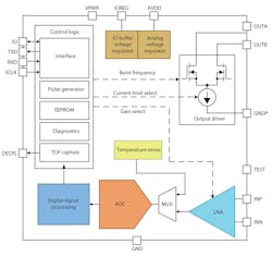
4. The PGA460-Q1, designed to be a part of a multiple-sensor ultrasonic system, offers a wide range of performance options. (Source: PGA460-Q1 PDF)
The four-step operation is as follows:
1. The analog front end buffers and amplifies the echo information and converts it to digital form via a 12-bit analog-to-digital converter (ADC).
2. An integrated DSP block then processes the digital data to extract the peak profile of the echo.
3. The output of the DSP is compared against the programmed threshold to measure the time of flight (TOF) for object distance calculation.
4. The result is transmitted over a USART or UART connection.
The automotive-qualified (AEC-Q100) device can detect objects at distances from 15 cm up to 11 meters. Depending on the transducer-transformer sensor pair selected, it’s possible to achieve a resolution of 1 cm. The product support includes an evaluation module (EVM) and a software development guide.
The PGA450-Q1 is a similar device to the PGA450, but integrates an 8015 microcontroller instead of the DSP. A reference design is available to help evaluate the PGA450-Q1. The design combines the PGA450-Q1 and an ultrasonic sensor on a small form-factor board.
Radar Sensing Fundamentals
In contrast to an ultrasonic sensor, an ADAS radar sensor uses electromagnetic (EM) waves to determine an object’s range, velocity, and angle in its field of view.
Various radar techniques are used to measure the range and velocity of an object. Texas Instruments applies the frequency-modulated continuous-wave (FMCW) method in its ADAS radar products.
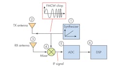
5. An FMCW radar transmits a synthesized chirp and combines it with the received signal to generate an IF signal that’s analyzed to determine the object range. (Source: EEwordsmith.com/TI ”Introduction to mmwave Sensing: FMCW Radars” PDF, p. 5, 17)
An FMCW radar transmit/receive (TX/RX) block works as follows (the numbers in Figure 5 correspond to those below):
1. A synthesizer generates a “chirp”—a sinusoid whose frequency increases linearly with time.
2. The chirp is transmitted by the TX antenna.
3. The chirp is then reflected by an object and received by the RX antenna.
4. A mixer combines the RX and TX signals to produce a composite IF signal.
5. A high-speed ADC digitizes the IF signal.
6. A DSP then performs a fast Fourier transform (FFT) to extract the frequency information, identify the objects, and determine their characteristics.
The RX signal is delayed by the time needed for the TX signal to travel to the object and return. The IF signal therefore contains the information required to measure distance and distinguish between different objects.
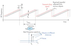
6. For each object, the IF signal contains a tone with frequency proportional to distance. (TI ”Introduction to mmwave Sensing: FMCW Radars” PDF)
Figure 6 shows the received FMCW signals. These comprise different delayed and attenuated copies of the transmit signal corresponding to various objects. Each object is a tone whose frequency (fb) is proportional to the distance of the object from the radar (R).
The process of detecting multiple objects and their respective distances from the radar involves taking a FFT of the IF beat-frequency signal and identifying the tones that correspond to detected objects.
The resolution of the FMCW architecture is a function of the chirp bandwidth. The AWR1x family of devices discussed later supports a chirp bandwidth of up to 4 GHz in a single sweep, giving a range resolution of less than 5 cm.
The IF bandwidth determines unambiguous velocity, which is the ability to separate objects with similar velocity. The radar front end in the AWR1x portfolio supports an IF bandwidth of 15 MHz, giving a maximum range of greater than 250 m (820 ft.) and an unambiguous velocity of up to 300 kph (186 mph).
You can read more about automotive radar sensor architectures in this white paper.
Automotive Applications of Radar Sensing

7. Automotive uses for radar include both short-range (blind-spot detection, backup parking) and long-range (adaptive cruise control, pre-crash detection) applications. (Source: Clemson University)
We can divide automotive radar applications (Fig. 7) into short-, mid- and long-range radars, based on the range of object to be detected:
- Ultra-short-range radar (USRR) is an emerging ADAS application for park-assist systems. These systems, part of SAE Level 1, typically use light-emitting diodes (LEDs) or steering-wheel vibration to warn drivers of obstacles.
- Driver-assist features such as lane-departure and blind-spot warnings employ short-range radar (SRR). Current SRR systems utilize the 24- to 29-GHz frequency band, but are expected to move to a higher frequency band in the future.
- Automatic emergency braking and adaptive cruise control use long-range radar (LRR) systems. Current LRR systems operate in the 76- to 77-GHz frequency range. Higher levels of automated driving demand higher range and resolution, so future front radar systems will likely use both the 76- to 77-GHz and 77- to 81-GHz frequencies and a combination of LRR and mid-range radar (MRR) systems.
Satisfying higher SAE automation levels will require radar sensors to analyze complex scenarios—detect hazards; measure their properties; and categorize them into groups with distinct properties (distance, velocity, angle, height, etc.)
Finally, the sensors must be able to coordinate with other systems so that the vehicle can take appropriate corrective action.
TI mmWave Portfolio
The AWR1x portfolio of millimeter-wave (mmWave) radar sensors from Texas Instruments contains three devices that satisfy different ADAS use cases, including USRR, SRR, MRR, LRR, and imaging. The portfolio supports two partitions: a smart sensor architecture, where all of the processing of radar signals occurs at the edge; and a satellite sensor architecture, in which the radar sensor transmits object data over the CAN-FD interface to a central processor for further processing and sensor fusion.
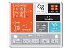
8. The mmWave sensor architecture integrates RF, analog, and digital technologies into a single device. (Source: “TI’s smart sensors designed for automated driving applications,” PDF, p. 3, Fig. 2)
All three devices use the mmWave sensing architecture (Fig. 8). This architecture combines a 32-bit ARM Cortex-R4F core, a digital signal processor (DSP) or hardware accelerator, radio-frequency (RF) circuitry, and digital control functions. It also includes built-in self-test (BIST) capability to help meet automotive ASIL B functional safety standards (ISO26262).
The three devices are:
- The AWR1243, a compact, high-performance radar front-end for medium-range and emerging applications. It includes three TX chains, each of which includes an independent binary phase modulation and variable-gain power amplifier with a simple single-ended output for direct interfacing to an antenna. Four RX chains include low-noise amplifier (LNAs), mixers, and a complex baseband with a 15-MHz IF bandwidth. In a typical application, the AWR1243 connects to one of TI’s TDA3x processors, and uses CSI-2 for data and SPI for control. By incorporating the C66x high-performance DSP and embedded vision engine (EVE) for efficient low-level radar processing, the TDA3x processor can handle the full bandwidth of the AWR1243.
- The AWR1443, a single-chip radar solution for proximity-sensing applications that integrates a hardware accelerator on-chip. It includes three TX chains and four RX chains. Typical proximity-sensing applications include door/trunk openers, ground clearance measurements, and in-cabin applications.
- The AWR1642, a single-chip radar solution that integrates a high-performance C674x DSP on-chip, together with two TX and four RX chains. Changing the programming model can enable a wide variety of sensor implementations (Short, Med, Long); implementing a multimode sensor is possible with dynamic reconfiguration.
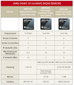
The AWRx family of mmWave radar sensors includes three devices aimed at different ADAS applications. (Source: “TI’s smart sensors designed for automated driving applications” PDF, p. 6)
The table above compares the features of the AWR1x devices. Figure 9 shows how the three devices fit into the ADAS landscape.
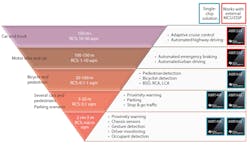
9. The devices in the AWR1x portfolio cover the short-, medium-, and long-range use cases for ADAS radar applications. (Source: “TI’s smart sensors designed for automated driving applications” PDF, p. 7)
Conclusion
FMCW radar technology has evolved significantly in the past several years, and is beginning to make inroads into more and more applications. These emerging applications in both driver convenience and safety are raising the performance bar for object detection and classification, velocity resolution, and spatial resolution. Programmable devices and embedded DSPs are allowing customers to differentiate their products via improved algorithms.
Ultrasonic sensors have been the standard choice for many years, and continue to improve with the addition of DSP capability to recent designs.
Radar will continue to dominate at longer distances. However, both technologies offer viable options for shorter-range applications.
About the Author
Paul Pickering
Paul Pickering has over 35 years of engineering and marketing experience, including stints in automotive electronics, precision analog, power semiconductors, flight simulation and robotics. Originally from the North-East of England, he has lived and worked in Europe, the US, and Japan. He has a B.Sc. (Hons) in Physics & Electronics from Royal Holloway College, University of London, and has done graduate work at Tulsa University. In his spare time, he plays and teaches the guitar in the Phoenix, Ariz. area
Comment About the Article
To join the conversation, and become an exclusive member of Electronic Design, create an account today!

Leaders relevant to this article: