Book Review: Understanding Automotive Electronics: An Engineering Perspective, Eighth Edition
Electrical engineers who want to be involved in the automotive industry should read Understanding Automotive Electronics: An Engineering Perspective, Eighth Edition, authored by William Ribbens. His firsthand experience as a research engineer provides the background for the subjects covered in the book. He is now Professor Emeritus of Electronic Engineering at the University of Michigan and Past Director, Vehicular Electronics Laboratory, University of Michigan. His intimate knowledge of automotive electronics is apparent in virtually every chapter of this 710-page book. Thoroughly updated throughout, this new edition covers current hot topics such as automotive camera systems, hybrid control, autonomous vehicles, software and vehicle networks, as well as:
- The full range of electrical/electronic theory that is applicable to modern automotive technology at a level progressing from basic theory and science, to detailed application for major automotive systems and components.
- Circuit/block diagrams representative of actual circuits employed in automotive electronic systems.
- A description of the AUTOSAR (AUTomotive Open System Architecture) software and how it integrates with automotive systems.
The first six editions of this book were written at a qualitative level in which automotive electronics was explained with minimal mathematics. Beginning with the seventh edition, this book was written with an engineering perspective that includes analytic models for automotive components and/or subsystems. The eighth edition follows a similar format with topics updated to reflect current automotive electronic technology.
Chapter 1 (Overview) identifies the chapters for each of the presented subjects, including electronic systems, subsystems, and individual components, and their associated technically detailed theory.
Semiconductor-based electronic components are covered in Chapter 2 (Electronic Fundamentals). It includes a qualitative description of the operation of all active devices and the presentation of an analytic model for each device. Engineering readers should be familiar with most electronic circuit components that are reviewed, such as solid-state devices, resistors, capacitors, and inductors.
Chapter 3 (Microcomputer Instrumentation and Control) describes how microcomputers are used in instrumentation and control systems. Included are inputs and outputs, computerized instrumentation, and computerized control systems. This is a good, concise description of microcomputer systems for automotive electronics.
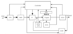
The first vehicular system controlled by electronics, engine control, is described in Chapter 4 (The Basics of Electronic Engine Control). Electronics for engine control reflects governmental regulations for exhaust emissions. Fig. 1 shows a typical electronic fuel control system.
Included in Chapter 4 are the basic concepts involved in controlling emissions for various operating conditions. It presents models of the engine performance and exhaust emissions. Dynamic engine analytic models enhance an understanding of control laws.
1. Electronic fuel control configuration with the following components:
TPS = Throttle position sensor
MAF = Mass airflow sensor
F I = Fuel injectors
IGN = Ignition systems
EGO = Exhaust gas oxygen sensor
ECS = Engine coolant sensor
Chapter 5 (Sensors and Actuators) explains modeling and performance analysis of these devices. Every electronic control system employed in vehicles fundamentally requires one or more sensor(s) and actuator(s). Subsequent chapters in this book discuss electronic control systems for such systems (powertrain, braking, steering, and suspension) all make reference to the appropriate set of sensor(s) and actuator(s) described in Chapter 5.
The entire vehicular powertrain, including the traditional engine transmission drive axle coupling for a conventional vehicle are covered in Chapter 6 (Digital Powertrain Control Systems). It includes a description of digital control electronics both qualitatively and quantitatively. This discussion concerns practical digital engine control electronics. In addition to the qualitative explanation, analytic models are developed for the control system with references to the basic discrete-time system theory of Appendix B.
This chapter describes hybrid/electric vehicles and the benefits of digital control and its ability to compensate for various engine-operating modes, including:
- Start-up
- Warm-up
- Acceleration
- Deceleration
- Cruise
- Environmental parameters (e.g., ambient air pressure and temperature)
The practical digital electronic engine control is capable of adapting to changes in vehicle parameters that can occur, for example, vehicle aging.
Chapter 7 (Vehicle Motion Controls) includes a description of vehicle dynamic motion. The subsystems involved in motion control include advanced cruise control, antilock braking systems, electronic suspension, electronic steering control, and traction control. Some of the components of the subsystems discussed in Chapter 7 are used in subsystems described and explained in other chapters.
Instrumentation is described in Chapter 8 (Automotive Instrumentation). In contemporary vehicles, many display devices only provide a visual (and often audio) warning to the driver when the variable is out of limits, and the vehicle requires either repair or possible addition of a fluid (e.g., engine oil). Another electronic instrumentation component is signal processing.
This chapter describes the specific signal processing for each example measurement discussed in vehicle instrumentation. Vehicular instrumentation includes single-variable measurement systems as well as multiple variables via a special-purpose computer. In contemporary vehicles, data for instrumentation along with other systems are passed along a dedicated vehicle network called “in-vehicle network” (IVN).
Vehicle communication systems both within the vehicle and with an external infrastructure (or potentially other vehicles) are described in Chapter 9 (Vehicle Communications). Communication systems in contemporary vehicles perform important functions for vehicle operation, for navigation, and for information plus its more traditional role of entertainment.
Chapter 9 covers four of the most commonly used IVNs incorporated (or in late stages of development) in contemporary vehicles. The communication media for these IVNs include wires, coaxial cable, and optical fibers. It is further explained how data are sent between the various electronic subsystems on board the vehicle. In-vehicle communication also is done using a wireless medium.
Both theory and the applications are discussed in this chapter. The IVNs discussed include the “controller area network” (CAN), “flex ray,” “local interconnect” (LIN), and “media-oriented systems transport” (MOST).
The ability of IVNs to enhance the performance of a given vehicular system by incorporating data from other subsystems is another issue. The ability of any subsystem to obtain data from another system can expand the analytic model for the system, which often expands its operating envelope and can improve precision and accuracy of the variable(s) being controlled.
Approaches for preventing or minimizing injuries to vehicle occupants in the event of an accident are included in Chapter 10 (Electronic Safety-Related Systems). This chapter discusses some relatively recent systems for preventing accidents.
Occupant protection systems include airbags that are an important supplement to seatbelts. It explains the theory of operation of an airbag system including a discussion of distinguishing an accident scenario requiring airbag deployment vs. other abrupt motion inputs to the vehicle.
Representative physical configurations are described qualitatively with illustrative figures. Block diagrams for the associated electronic systems are presented along with analytic models for the various components.
This chapter also includes a review of the earliest airbag configurations to provide a reference for the significant improvements in occupant safety that have occurred. Also described are the technological advances in both sensing and signal processing for proper crash detection.
Chapter 11 (Diagnostics) covers problems in vehicles via electronic systems or subsystems that assist technicians in repairing vehicles. Electronic diagnostic capability exists in the vehicle electronic systems themselves and in service-bay systems (auto dealerships). From the earliest days of digital control systems, the controlling computer has had some self-diagnostic capability. For such control systems, the corresponding fault code is stored in memory once a failure or malfunction is detected by the system. The fault codes can be downloaded to a service-bay system for the purpose of diagnosing vehicle system problems.
Besides assisting the servicing of vehicles, governmental regulations require vehicles to have certain self-diagnostic capabilities (“on-board diagnostics” or OBD). OBD requirements pertain to malfunctions that affect vehicle exhaust emissions. One such requirement is called misfire detection, which refers to improper combustion that can cause an incorrect air/fuel mixture, or possibly a failed spark plug. The EPA requires that misfires be detected and that a warning message be displayed so the driver can have the powertrain repaired if misfires exceed a specified threshold.
Chapter 12 (Autonomous Vehicles) discusses the current R&D available at the time of this writing. The autonomous vehicle will be controlled by a computer and various automatic subsystems. Autonomous vehicles are classified in multiple levels depending on the amount of driver action required. At the lowest level, a driver must observe the environment and make normal driving decisions. At the highest level, no action is required by a driver, and the vehicle becomes entirely autonomous.
Virtually all the vehicle automatic systems required for an autonomous vehicle are already developed. An important automatic subsystem required for an autonomous vehicle that is not covered in previous chapters is automatic steering, which is available in very limited form in some production vehicles. This existing automatic steering is of the form of automatic parallel parking and automatic lane tracking. Analytic models for automatic steering (with parallel parking as an example) are developed, and hardware components are described, including physical configurations and models that are explained in detail.
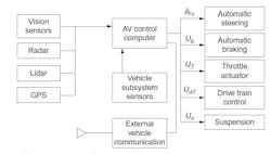
This chapter presents a representative block diagram of an autonomous vehicle (Fig. 2). It depicts the automatic systems as blocks and presents a set of sensors required. Besides the sensors required to successfully control each automatic system, a set of sensors is depicted that provide the data and information required for the complete system to evaluate the environment surrounding the vehicle with a full 360 degrees field of view. These sensors include the vehicular radar, lidar, and camera systems (with image identification software) that are discussed with respect to blind spot detection in Chapter 10. Any fully autonomous vehicle must have detailed information on its surrounding environment that includes lane tracking and other vehicle and obstacle detection.
2. Representative autonomous vehicle.
Appendices
Appendix A: The Systems Approach to Control and Instrumentation
Appendix B: Discrete Time Systems Theory
Appendix C: Dynamics in Moving Coordinate Systems
Appendix D: FDI Feedback Matrix Design
Appendix E: Coordinate Transformation
Appendix F: GPS Theory
Book Information
Paperback ISBN: 9780128104347
eBook ISBN: 9780128104354
Imprint: Butterworth-Heinemann
Published Date: 18th June 2017
Page Count: 710
For information on all Butterworth-Heinemann publications, visit the website at: https://www.elsevier.com/books-and-journals.
About the Author

Sam Davis
Sam Davis was the editor-in-chief of Power Electronics Technology magazine and website that is now part of Electronic Design. He has 18 years experience in electronic engineering design and management, six years in public relations and 25 years as a trade press editor. He holds a BSEE from Case-Western Reserve University, and did graduate work at the same school and UCLA. Sam was the editor for PCIM, the predecessor to Power Electronics Technology, from 1984 to 2004. His engineering experience includes circuit and system design for Litton Systems, Bunker-Ramo, Rocketdyne, and Clevite Corporation.. Design tasks included analog circuits, display systems, power supplies, underwater ordnance systems, and test systems. He also served as a program manager for a Litton Systems Navy program.
Sam is the author of Computer Data Displays, a book published by Prentice-Hall in the U.S. and Japan in 1969. He is also a recipient of the Jesse Neal Award for trade press editorial excellence, and has one patent for naval ship construction that simplifies electronic system integration.
You can also check out his Power Electronics blog.


