Tester Assesses Automotive Radome mmWave Transparency

When engineers hear the term “radome,” they will usually visualize those large bubble-like domes protecting radar and data-link dish (or other) antennas from the elements. Despite their simple appearance, a conventional radome is a complex electronic and mechanical structure that must withstand wind, water, sun, and more, while its internal support elements must cause minimal disturbance to the antenna RF field. Furthermore, the enclosing material must be RF transparent at the frequencies in use.
But not all radomes are so obvious and visible. Today’s cars, with their use of 77- and 79-GHz bands (millimeter wave or mmWave) for radar and other advanced driver-assistance systems (ADAS) functions, also contain many smaller radomes used to conceal and protect the tiny antennas while also reducing drag. How can an automotive design know that the radome in use, such as a brand emblem or rear-view mirror housing, is actually transparent to RF at the designated frequencies?
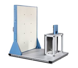
1. The QAR System from Rohde & Schwarz allows for evaluation of automotive radome performance in the crucial 77- and 79-GHz bands.
The solution is to test these tiny radomes, and that’s where the QAR system from Rohde & Schwarz plays a role (Fig. 1). This imaging radome tester enables users to check, under automated control, various performance parameters such as RF transparency and homogeneity of these shell-like radomes.
These measurements indicate if sensor performance will be diminished or affected by the enclosure, and if other RF-based ADAS subsystems will work as planned with respect to factors such as sensitivity, range, intended coverage, and other parameters. Otherwise, reflections and attenuation in the radar sensor’s field of view will considerably impair sensor performance (Fig. 2). As explained in the reference provided below, even minute changes in thickness and other dimensions of the automotive radome can have a significant effect on its RF performance.
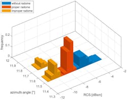
2. The influence of different radomes on radar cross section (RCS) and angle of incidence shows unsuitable radomes can cause angle errors.
Any defects in the77- and 79-GHz bands’ images of the QAR correspond directly to radar-signal impairments. The R&S QAR supports all material designs and form factors up to 30 × 50 cm, operates as an automated test center, supports full remote-control operation, and can be integrated into larger automated-test systems.
Reference
Rohde & Schwarz: Dr. Steffen Heuel; Tobias Köppel; Andreas Reil; Dr. Sherif Ahmed, “Enabling autonomous driving”

About the Author

Bill Schweber
Contributing Editor
Bill Schweber is an electronics engineer who has written three textbooks on electronic communications systems, as well as hundreds of technical articles, opinion columns, and product features. In past roles, he worked as a technical website manager for multiple topic-specific sites for EE Times, as well as both the Executive Editor and Analog Editor at EDN.
At Analog Devices Inc., Bill was in marketing communications (public relations). As a result, he has been on both sides of the technical PR function, presenting company products, stories, and messages to the media and also as the recipient of these.
Prior to the MarCom role at Analog, Bill was associate editor of their respected technical journal and worked in their product marketing and applications engineering groups. Before those roles, he was at Instron Corp., doing hands-on analog- and power-circuit design and systems integration for materials-testing machine controls.
Bill has an MSEE (Univ. of Mass) and BSEE (Columbia Univ.), is a Registered Professional Engineer, and holds an Advanced Class amateur radio license. He has also planned, written, and presented online courses on a variety of engineering topics, including MOSFET basics, ADC selection, and driving LEDs.
Comment About the Article
To join the conversation, and become an exclusive member of Electronic Design, create an account today!

Leaders relevant to this article: