Step back for a moment and marvel: In just a few years, we’ve transitioned from no cameras in cars to having multiple ones—an amazing rate of progress. These cameras need multiple voltage rails and thus power-management ICs (PMICs), and the rails must be optimized for the challenging power, size, and operating requirements of the vehicular environment.
Focusing on this well-defined and very large opportunity, the MAX20049 PMIC developed by Maxim Integrated Products squeezes four power regulators—two buck, two LDO—into a total footprint claimed to be the smallest available for this application while also delivering highest competitive efficiency.
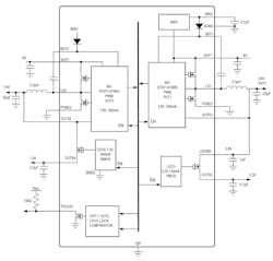
This PMIC (Fig. 1) incorporates two 500-mA step-down (buck) converters and two LDOs (400 mA and 100 mA) in a 3- × 3-mm package with a total function footprint of 38 mm2, compared to 53.3 mm2 for alternative offerings. In addition, it includes features not found elsewhere in this class of product, such as overvoltage protection (OVP), undervoltage lockout (UVLO), external power-good (PG) signal, and cycle-by-cycle current limiting. Best-case efficiency is 74% at full load, greatly reducing the thermal burden.
1.The MAX20049 PMIC from Maxim Integrated Products fits two buck switching converters and two LDOs into a 3- × 3-mm package.
Of course, the input and output voltage specifications are the items of first interest. The two internal, fixed-frequency, pulse-width-modulated (PWM) buck converters operate at input voltages from 5 to 17 V (for the MAX20049) or 4 to 17 V (MAX20049C), compatible with power-over-coax (PoC) that typically uses 8 to 10 V. (There’s also an option of using one of the buck converters as an intermediate supply for generating typical sensor plus serializer rails.) The buck converters are designed to operate 180 deg. out-of-phase with each other to minimize input-current ripple.
Output voltages are factory set and cover the needs of different sensor imagers, including 3.3, 3.0, 2.9, 2.8, or 2.7 V, while the secondary supplies cover the typical 1.8-, 1.2-, 1.1-, and even sub-1.0-V rails for the serializer and memory. The 2.2-MHz switching frequency enables the use of physically small, low-cost ceramic capacitors, and these PMICs feature a spread-spectrum mode option to attenuate EMI and meet CISPR (Comité International Spécial des Perturbations Radioélectriques; in English: International Special Committee on Radio Interference) noise restrictions. The 16-lead MAX20049 comes in a TQFN package with an exposed thermal pad and is AEC-Q100 qualified.
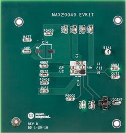
2. Supporting design-in with the MAX20049, the corresponding MAX20049EVKIT# evaluation kit provides standard outputs of 3.8 V, 1.8 V, 3.3 V, and 1.3 V from an input rail up to 17 V.
For design support, Maxim offers EE-Sim models for design and simulation of the MAX20049. In addition, the company offers the MAX20049EVKIT# evaluation kit (Fig. 2), a fully assembled and tested application circuit that provides four output voltages from a single input rail, which can range up to 17 V. It’s pre-populated with the MAX20049ATEA/VY+ version for outputs of 3.8 V, 1.8 V, 3.3 V, and 1.3 V; other MAX20049 options are available.
About the Author

Bill Schweber
Contributing Editor
Bill Schweber is an electronics engineer who has written three textbooks on electronic communications systems, as well as hundreds of technical articles, opinion columns, and product features. In past roles, he worked as a technical website manager for multiple topic-specific sites for EE Times, as well as both the Executive Editor and Analog Editor at EDN.
At Analog Devices Inc., Bill was in marketing communications (public relations). As a result, he has been on both sides of the technical PR function, presenting company products, stories, and messages to the media and also as the recipient of these.
Prior to the MarCom role at Analog, Bill was associate editor of their respected technical journal and worked in their product marketing and applications engineering groups. Before those roles, he was at Instron Corp., doing hands-on analog- and power-circuit design and systems integration for materials-testing machine controls.
Bill has an MSEE (Univ. of Mass) and BSEE (Columbia Univ.), is a Registered Professional Engineer, and holds an Advanced Class amateur radio license. He has also planned, written, and presented online courses on a variety of engineering topics, including MOSFET basics, ADC selection, and driving LEDs.


