Download this article in PDF format.
The real objective in developing electric vehicles (EVs) is to offer models with positive characteristics that encourage people to actually buy them. Higher efficiency and greater power density are your key design goals. However, as an EV designer, you must also address the weaknesses and limitations that discourage the purchase of an EV.
The number one and number two consumer issues are “range anxiety” and excessive charging time. Consumers aren’t happy with short-range limitations that will force them to constantly worry about dying batteries and finding that rare nearby charging station.
Most people have internal-combustion-engine (ICE) vehicles that can achieve a range of 300 to 400 miles on a tank of gas. Furthermore, they know gas stations are always nearby to fill up the tank. And that fill-up only takes 5 to 10 minutes compared to at least a half-hour of charge time.
EVs are gradually zeroing in on a solid 200- to 300-mile range and no doubt there are plans for a nationwide charging station rollout. Both will continue to improve. The real solution, of course, is a better battery. Lithium-ion batteries aren’t only the current choice, but also the only practical choice—for now.
Automotive engineers also know that the remaining problem is charging time. It takes a minimum of 30 minutes to an hour to fully recharge an EV battery with high-voltage (HV) dc. That’s simply unacceptable. Home chargers help mitigate this problem with regular overnight charges, but wouldn’t it be nice if a visit to a charging station only took a few minutes to recharge.
As it turns out, faster charging is a real priority objective. And even that has some limitations. Here’s a look at some of the technology helping to address these limitations.
Sponsored Resources:
- How to charge your EV faster
- A Design Review of a Full-Featured 350-W Offline Power Converter
- Reference design: Vienna rectifier-based three phase power factor correction
EV Charging Basics
There are several types of EV battery charging. The charging equipment is referred to as the electric-vehicle service equipment (EVSE); it can be a home system or one of several at a charging station. Charging stations are also referred to as a pile.
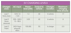
The other part of the system is the charger. It can be an onboard charger (OBC) built into the vehicle or an external charger. The Society of Automotive Engineers (SAE) currently defines three classes or levels of vehicle charging (see table).
Level 1 and 2 chargers are OBCs that are built into the vehicle itself. Standard single- or two-phase ac powers the OBCs, which convert the ac into dc to charge the battery. Charging times are lengthy but probably satisfactory for overnight charging. Current charging stations offer Level 2 and Level 3 chargers. Their fast chargers use three-phase ac and convert it into HV dc to charge the battery directly. These HV dc systems greatly shorten charge time to 30 minutes or so.
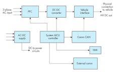
Figure 1 shows a general block diagram of a Level 3 dc charger. The three-phase input may be 240- or 480-V, 50- or 60-Hz ac. It’s applied to an ac-to-dc power supply that furnishes all of the low-voltage dc that powers the internal circuitry. Next, the three-phase input is power-factor-corrected (PFC). Subsequently, a dc-dc converter then produces the high dc output voltage in the 400- to 800-V range. This voltage is connected to the vehicle through an interface with a standardized plug.
1. Shown is a general block diagram of a Level 3 HV dc EVSE.
In addition to the HV dc connection, the plug also establishes a communication link between the EVSE and the vehicle, usually via a controller area network (CAN) port. The vehicle and the charger exchange data including battery type and the correct battery-charging profile. Everything is organized and coordinated by a master controller, usually an MCU. Additional features include a human-machine interface (HMI), which is often an LCD display with touchscreen capability that provides communications with the charging customer. An external interface (RS-485 or Ethernet) connects the EVSE to the outside world.
All that said, the real design challenge is to develop the charger that shortens charge time. However, some of that problem has to do with the nature of the battery chemistry and not the electronics.
How to Charge Your EV Faster
While range anxiety is a major obstacle to EV adoption, consumers are also concerned about the necessity for decreased charging time. Who wants to wait a half-hour or more at a charging station? And that’s on top of the waiting in line behind other vehicles trying to access what may be a single EVSE.
The factors that improve fast charging are more efficient power transfer and increasing power levels in both on- and off-board chargers. For example, higher system voltages (>400 V) permit energy transfer more efficiently. Designers have now discovered newer semiconductor devices with low losses and high-voltage tolerance as well as low on-resistance and high thermal conductivity that can serve such requirement:
The Silicon-Carbide MOSFET
Up until recently, the switching power needs of EVs have been met with silicon power MOSFETs and IGBTs. However, both of these devices have topped out in their high-voltage/high-current capabilities and switching speeds.
Luckily, the silicon-carbide (SiC) FET has emerged as the successor to these devices. This wide-bandgap device offers lower power loss, higher frequency operation, higher voltage operation, increased heat dissipation, and higher junction temperatures. The SiC MOSFET can operate at voltages up to 1500 V and higher currents, all the while switching faster and lowering power consumption with its lower on-resistance.
Unlike silicon MOSFETs and IGBTs, the SiC FET requires a higher gate-drive voltage in the 15- to 20-V range and a negative turn-off voltage. Special gate drivers are needed. The driver is the interface between the circuit controller (usually an MCU) and the device. The driver amplifies the controller outputs and conditions the drive signal to operate the SiC device.
Gate drivers also provide galvanic isolation between the driving and driven circuits to prevent unwanted direct-current flow. Capacitive coupling is one preferred method of implementing the isolation as it blocks dc, but allows signals to pass.
Texas Instruments makes a family of isolated gate drivers for SiCs. Designated as the UCC217xx series, these devices solve the problem of gate drive, allowing SiCs to power future chargers, inverters, and other switching circuits for EVs.
Microcontroller-Based Switch-Mode Power Devices
Equipping on- and off-board battery chargers and other switch-mode power devices with at least one microcontroller or microcontroller unit (MCU) is becoming a standard practice. The flexibility of the MCU makes it a highly desirable addition to most new automotive power equipment.
For example, by using an analog-to-digital converter (ADC), parameters such as mains voltage and current, PFC voltage and current, multiple temperature measurements, and others can be sampled and digitized for use by the microcontroller. The MCU is also used to enable and disable all of the circuits.
In addition, the MCU generates the pulse-width-modulated (PWM) signals that operate and synchronize the signals in all circuits including the PFC. Moreover, the microcontroller can implement a full HMI with LCD display and control pushbuttons.
For more details take a look at the referenced link below that shows a complete, state-of-the-art, high-performance/high-efficiency power-supply system that incorporates monitoring, safety functions and interfacing with a microcontroller.
Vienna Rectifier Implements PFC
Most switch mode power supplies must now incorporate power factor correction. Briefly, PFC is the process of controlling and shaping the incoming line current so that it’s sinusoidal and in phase with the mains voltage. This ensures a PF close to unity and a decrease in rectification distortion that minimizes harmonics getting back on the power line. One of the best ways to implement PFC in a three-phase switch-mode supply is to use a Vienna rectifier.
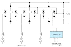
Vienna rectifier power topology is used in high-power, three-phase power-factor (ac-dc) applications such as off-board EV chargers. Most Vienna rectifiers employ three diode bridges each with a control MOSFET driven by a PWM signal. Design of these rectifiers is complex (Fig. 2). The MOSFETs switch at a rate of 20 to 50 kHz with PWM from the controller, so that the average current drawn from each phase is sinusoidal and in phase with its voltage.
2. A simplified Vienna rectifier translates its three-phase ac input into high voltage that powers the dc-dc converter to charge a battery.
One can address this design challenge by adopting Texas Instruments’ TIDM-1000 reference design. This design uses a C2000 microcontroller to control a Vienna rectifier. It’s a good way to speed up and simplify your design of three-phase EV chargers.
Sponsored Resources:
About the Author

Lou Frenzel
Technical Contributing Editor
Lou Frenzel is a Contributing Technology Editor for Electronic Design Magazine where he writes articles and the blog Communique and other online material on the wireless, networking, and communications sectors. Lou interviews executives and engineers, attends conferences, and researches multiple areas. Lou has been writing in some capacity for ED since 2000.
Lou has 25+ years experience in the electronics industry as an engineer and manager. He has held VP level positions with Heathkit, McGraw Hill, and has 9 years of college teaching experience. Lou holds a bachelor’s degree from the University of Houston and a master’s degree from the University of Maryland. He is author of 28 books on computer and electronic subjects and lives in Bulverde, TX with his wife Joan. His website is www.loufrenzel.com.


