Updating EV Battery Management for LFP: 10 Key Questions
What you'll learn:
- The main differences between traditional lithium and lithium-iron-phosphate (LFP) cells.
- The specific changes in measurement and SOC assessment required for LFP
- The other ways to optimize adoption of LFP and ensure the best results.

1. Why Does LFP Change the BMS Design Game?
Lithium-iron-phosphate (LiFePO₄, or LFP) cells, an important variation on the lithium battery chemistry theme, are no longer confined to buses, forklifts, and stationary storage. They’re now increasingly mainstream in passenger EVs, commercial fleets, and hybrid architectures.
Their appeal is clear: excellent cycle life, thermal stability, lower raw-material risk, and reduced fire propensity.
Tesla wasn’t the first to adopt LFP. However, the company has since made them a central part of its product lineup, supplemented by use of lithium nickel-manganese-cobalt oxides (NMC), which have further enhanced characteristics over LFP. But not everyone has made the move.
LFP chemistry breaks many assumptions embedded in legacy EV battery-management system (BMS) designs. Simply reusing an existing BMS with different voltage limits leaves performance, longevity, and diagnostic capability on the table for potential optimization.
Optimizing a BMS for LFP requires revisiting voltage sensing, state-of-charge (SOC) estimation, balancing strategies, thermal logic, fault thresholds, and even hardware architecture. This article outlines some of the key design changes potentially required to update existing systems for LFP successfully.
2. What are the Fundamental Electrical Differences that Come with LFP?
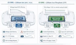
The most consequential electrical distinction is LFP’s flat open-circuit voltage (OCV) curve across much of its usable SOC range. Between roughly 20% and 80% SOC, cell voltage changes only tens of millivolts. By contrast, other chemistries typically exhibit a steeper OCV-SOC relationship, enabling voltage-based SOC estimation and passive balancing triggers.
The design implications include:
• Voltage alone is insufficient for SOC estimation.
• Small measurement errors translate into large SOC uncertainty.
• Traditional top-of-charge voltage balancing is less informative.
3. How Can SOC Estimation Move Beyond Voltage Heuristics?
Coulomb counting is likely mandatory, but it may not be enough. Most existing EV BMS already implement coulomb counting. With LFP, it becomes the primary SOC estimator, not a secondary correction mechanism.
Design updates could include:
• Higher-accuracy current sensing (≤0.5% full-scale error preferred)
• Lower drift amplifiers and ADC references
• Continuous offset calibration during rest periods
Hybrid SOC models are required to avoid long-term drift:
• Combine coulomb counting with model-based observers (Kalman filters, extended observers)
• Use temperature-compensated OCV lookup tables only at known rest states
• Integrate impedance-based estimation during controlled excitation events (regen pulses, load steps)
The key point is that SOC estimation for LFP batteries is a system-level algorithm problem, not a sensing-only problem.
4. What is Cell Voltage Measurement Accuracy Over Range?
Existing BMS designs often emphasize wide voltage range (e.g., 2.5 to 4.3 V) at modest resolution. LFP requires the opposite. Recommended changes might include:
• Narrower measurement span (e.g., 2.0 to 3.8 V)
• Increased ADC resolution (16-bit preferred)
• Tighter per-channel gain matching
• Improved common-mode rejection during switching events
A 5-mV error in an NMC system is tolerable. In an LFP system, it can mask meaningful SOC or balancing decisions.
>>Download the PDF of this article, and check out the TechXchange for similary themed articles and videos


5. When and How Should Cell Balancing be Rethought?
Passive cell balancing still works — but it needs re-timing. Because LFP cells spend little time near a sharp voltage knee:
• Passive balancing should occur over longer durations
• Trigger thresholds should be SOC- or capacity-based, not voltage-only
• Balancing during mid-SOC rest periods may be more effective than top-of-charge
Active balancing becomes more attractive. The long cycle life of LFP increases the ROI of:
• Capacitive or inductive active balancing
• Module-to-module energy redistribution
• Balancing during drive or regen events
For retrofits, even low-power active balancing (0.5 to 1 A) can significantly reduce pack drift over thousands of cycles.
6. How Does Thermal Management Stability Change the Control Strategy?
LFP cells are intrinsically more thermally stable than traditional Li-ions and feature higher thermal-runaway onset temperatures, exhibit less heat generation at moderate C-rates, and have better tolerance of partial-state cycling. However, they’re not thermally immune.
Cold-temperature charging is the real risk. LFP chemistry is particularly sensitive to:
• Lithium plating during cold charging
• Increased impedance below ~0°C
To counteract these unique properties, the BMS typically needs to be updated to include more conservative cold-charge current limits and temperature-dependent charge acceptance curves. It’s also mandatory to employ pre-heating logic for fast charging in cold climates.
This shifts thermal control emphasis from overtemperature protection to low-temperature charge protection.
7. What are the Issues with Charge Control and Voltage Limits?
Engineers can expect narrower safe operating windows with LFP batteries. Typical LFP limits:
• Max charge: ~3.55 to 3.65 V/cell
• Nominal: ~3.2 to 3.3 V/cell
• Discharge cutoff: ~2.5 to 2.8 V/cell (application-dependent)
The solution is to use tighter charger communication tolerances, adopt faster fault detection for overvoltage events, and reduce the system’s reliance on voltage tapering for charge termination.
Many legacy chargers rely on voltage rise to signal near-full SOC — this must be replaced with SOC- or charge-integrated termination logic.
8. How Do Fault Detection and Diagnostics Change?
LFP’s failure modes are quieter electrically but more subtle diagnostically.
Key diagnostic enhancements:
• Track capacity fade, not just resistance rise
• Monitor imbalance growth rate over time
• Detect loss of active material via coulombic efficiency trends
• Flag abnormal relaxation behavior after load removal
Because LFP cells often fail “gracefully,” degradation detection becomes a data analytics problem, not a protection problem.
9. What are Implications for Pack Architecture and Series Count?
Because LFP cells have lower nominal voltage, more cells are required in series for the same pack voltage. Moreover, cell count increases ~20% to 25% compared to NMC.
These changes to the construction of the battery pack not only requires a BMS with a higher channel count, but it also impacts the isolation design, boosts the complexity of the wiring harness, and increases daisy-chain communication latency.
Existing BMS hardware may need:
• Expanded monitor IC capacity
• Repartitioned module architecture
• Retuned isolation measurement thresholds
10. How Can Fire Prevention and Other Issues be Addressed?
LFP’s improved safety profile allows design teams to rebalance priorities:
• Less aggressive thermal derating
• Fewer nuisance shutdowns
• Greater emphasis on uptime and cycle efficiency
However, regulators and OEM safety cases often lag chemistry reality. Therefore, BMS designs must still meet legacy functional-safety requirements, even if the risk profile is actually lower.
For OEMs retrofitting LFP into existing EV platforms:
• Most changes are software-dominant, not hardware-dominant
• SOC algorithms, thermal maps, and balancing logic are primary levers
• Hardware upgrades are mainly required for measurement accuracy and channel count
A phased engineering approach likely works best:
1. Measurement validation
2. SOC algorithm replacement
3. Balancing strategy update
4. Thermal and charge control tuning
5. Long-term degradation modeling
LFP batteries reward engineers who design for accuracy, long-term observability, and algorithmic sophistication rather than brute-force voltage thresholds. Existing EV BMS designs can be adapted successfully, but only if teams acknowledge that LFP isn’t “just another lithium cell.”
When optimized properly, LFP-compatible BMS architectures deliver exceptional cycle life, predictable aging behavior, high safety margins, and lower total cost of ownership.
For engineers willing to rethink legacy assumptions, LFP offers a rare opportunity to build simpler, safer, and longer-lived EV energy systems — but only if the BMS evolves with the chemistry.
References
The battery chemistries powering the future of electric vehicles
Recent Advances in Lithium Iron Phosphate Battery Technology: A Comprehensive Review
>>Download the PDF of this article, and check out the TechXchange for similary themed articles and videos
About the Author

Alan Earls
Contributing Editor
Comment About the Article
To join the conversation, and become an exclusive member of Electronic Design, create an account today!

Leaders relevant to this article: