E-Meters Offer Multiple Ways to Combat Electricity Theft and Tampering
Stealing electricity has been around since shortly after Thomas Edison founded the Edison Electric Light Company in New York City in 1878. In 1886, for example, the Daily Yellowstone Journal reported that “numerous unprincipled persons had availed themselves of the opportunity to steal electricity” from Edison by tapping into the wires upstream of the electrical meter. The superintendent of the electrical company responded by connecting extra electrical dynamos into the system in an attempt to burn out the illicit coils and motors.
The problem continues to this day. According to a recent study, global losses from electricity theft in 2015 totaled US$89.3 billion. India led the way ($16.2 billion in losses), followed by Brazil ($10.5 billion) and Russia ($5.1 billion).
With the adoption of the Smart Grid and smart meters, though, utilities are introducing new technologies to detect meter tampering and reduce electricity theft.
Common Tampering Methods
Electricity thieves have numerous ways to ply their trade. The simplest approach is to connect into power lines before the electrical meter; thieves can also bypass the meter altogether. More sophisticated schemes aim to reduce the amount of consumption recorded by altering the connections to the meter, or tampering with the operation of the meter itself.
External wiring modifications include swapping phase and neutral wires; disconnecting the neutral wire altogether; providing a return path via ground rather than neutral; and disconnecting one of the phase wires from the meter.
When it comes to tampering with the meter’s internal operation, a strong magnet is the aspiring evil-doer‘s best friend. Electrical meters use magnetic devices in voltage- and current-measurement circuits, and are susceptible external magnetic fields. Placed next to a meter, a powerful magnet can saturate the sensor magnetic cores and introduce large errors in measurement, or even disable the meter completely by interfering with its power-supply transformer.
Smart Meter to the Rescue
Over the last decade, electric companies have been replacing traditional electromechanical meters with electronic “smart meters,” or e-meters, that precisely record electricity consumption and communicate it back to the utility. A smart meter typically includes a microcontroller (MCU)-based data-acquisition system to measure voltage and current, a real-time clock to time-stamp information, a bidirectional wired or wireless communications system, fault reporting and diagnostic capability, and of course, various methods to detect electricity theft and meter tampering.
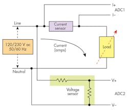
Figure 1 shows the typical approach to measuring current and voltage by means of analog-to-digital converters (ADCs) interfacing to the MCU. The circuitry must keep power consumption to a minimum, so the microcontroller typically spends much of the time in a low-power or sleep state and wakes up only to perform a measurement, send or receive data, or respond to an alert.
Anti-Tampering Measures
A smart meter uses multiple methods to detect and prevent tampering. Of course, the meter case should be sealed to prevent easy access, with no spaces to insert foreign objects. In the event of unauthorized access, though, a button can be added to the case that alerts the microcontroller whenever the case is opened.
To deal with electricity thieves specifically bypassing current on the live channels, the e-meter measures the current on the neutral channel and compares it to the live current.
For a single-phase meter, the two currents should be equal under ideal conditions. If a significant mismatch is seen, this may indicate that a tamper event has occurred.
For a three-phase meter, the neutral current should ideally be zero if loads are balanced for all phases. A large current on the neutral channel can also indicate tampering.
Protecting Sensors Against Magnetic Tampering
One potential point of attack is against the meter’s current transformer (CT).
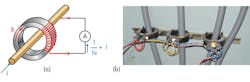
A CT is a popular way to measure current consumption. As illustrated in Figure 2a, the alternating current in the primary produces a magnetic field B in the CT core, which then induces an alternating current in the secondary. If the primary is a wire carrying a current I, the current in the secondary is I divided by N, the number of turns of the secondary coil. The current transformer output is isolated from the potentially lethal voltages and currents in the primary wire.
Applying a strong external magnetic field can cause the CT core to saturate, introducing errors or rendering it inoperative.
There are multiple ways to combat magnetic attacks aimed at current transformers. If the CTs are internal to the meter, it may be possible to orient them so that it’s difficult to place a magnet in close proximity. If not, the locations can be shielded to reduce the effect of a magnetic field.
Another alternative is to replace the CTs with Rogowski coils. This device consists of a helical coil of wire with the lead from one end returning through the center of the coil to the other end, so that both terminals are at the same end of the coil. The coil is then wrapped around the current-carrying wire. The measurement is still isolated, but since there is no metallic core the Rogowski coil is largely immune to magnetic tampering.
Measuring the current-induced voltage across a shunt resistor is another possibility. It can provide a precise result, but since it’s a direct measurement technique, the signal must be isolated from the rest of the circuitry. The AMC1304 is an isolated precision delta-sigma modulator that’s suitable for this purpose—it can achieve 16-bit resolution and a dynamic range of 81 dB (13.2 ENOB) at a data rate of 78 ksamples/s.
Yet another option is to place a sensor next to the vulnerable component to detect the presence of an external magnetic field. The DRV5033, for example, is a chopper-stabilized Hall-effect sensor that indicates the presence of a magnetic field. When the applied magnetic flux density exceeds a defined threshold, regardless of polarity, the open-drain output goes low to alert a microcontroller. Three DRV5033s may be connected together for 360° protection.
Protecting the Power Supply
A power transformer is a key element in both isolated and non-isolated switching topologies, and is subject to the same magnetic disruption as a current transformer. In a power supply, a successful attack may disable the e-meter completely unless preventative measures are taken.
If the e-meter is parsimonious in its use of power, one option for the power supply is to implement a drop-cap topology, which doesn’t require a transformer. A drop-cap power supply uses the capacitive reactance of a capacitor to reduce the mains voltage to a lower level.
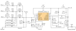
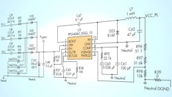
Figure 3 shows the schematic of a drop-cap power supply suitable for a three-phase e-meter. The design uses the TPS54060, a 60-V/0.5-A step-down regulator with an integrated high-side MOSFET. It allows all three phases to contribute to the current drive, giving approximately three times the drive of a single-phase solution.
The input circuit for each phase consists of three components: the input capacitor (C39 for Phase 1) that drops the line voltage down to a value based on the capacitive reactance; a series resistor (R92) that limits current; and a Zener diode (D21) that clamps the input voltage on the positive ac cycle and discharges C39 on the negative ac cycle. The values of C39 and R92 are chosen based on the required output-current drive of the power supply.
The outputs of the three phases are rectified to charge capacitor C102 and form the dc supply voltage to the dc-dc converter. If a higher output drive is required, an NPN output buffer can be added.
The capacitive-drop topology is cheaper than a transformer-based design and takes up less space. However, it has two limitations that should be taken into account.
First, since the capacitor must be able to withstand the full ac line voltage across it and the deliverable current is proportional to the capacitance value, it must have both a high voltage rating and a high capacitance value. It’s an expensive combination, so this topology tends to be limited to low-power applications.
Second, because there’s no transformer, it’s a non-isolated topology. Therefore, the circuit must be encapsulated and isolated to avoid direct (galvanic) contact with users.
For higher currents, a transformer-based topology may be unavoidable, but suitable precautions—shielding, location, etc.—must be taken. To guard against a successful attack disabling the meter, there must be a backup source of power, such as a battery, to maintain operation long enough to log the attack and alert the utility.
Anti-Tampering Reference Design
Figure 4 shows the block diagram of a reference design that incorporates many of the anti-tampering features discussed earlier. The design gives the designer a choice of either a TPS54060 capacitive-based power supply or a power supply using a transformer and the UCC28910 flyback switching regulator.
For the transformer-based power supply, Hall-effect sensors sit near the transformer to detect magnetic tamper attempts. If main power is lost due to magnetic tampering, the system can switch to a backup power source to maintain functionality.
If the backup power source is a battery, it’s important to reduce the current consumption of the Hall sensors to prolong battery life. This current consumption reduction is accomplished by duty-cycling the power to each Hall sensor.
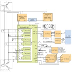
The design uses the MSP430F67791A MCU. It includes a range of low-power modes, multiple high-precision sigma-delta (ΣΔ) ADCs, and input-capture pins to log the time of an event, such as an unauthorized case opening, even when the main power to the e-meter isn’t available.
The reference-design software has an option to calculate usage based on a large predefined current value, instead of the sensed value, once a large magnetic field is detected.
A Continuing Game
Although the problem of electricity theft is greatest in India and Brazil, don’t think that it’s confined to developing countries. In Canada, for example, BC Hydro estimated losses in 2013 to be around 3% of production, or 850 GWh. That’s enough power to supply 77,000 homes, with a value of $100 million.
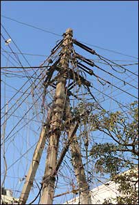
The biggest culprit? Marijuana growers. In an effort to avoid detection by both the utility and law enforcement, they’ve resorted to sophisticated schemes, including tapping directly into 12- or 25-kV lines, installing transformers, hollowing out utility poles, and running underground lines directly to their operations.
With techniques such as we’ve described above, smart meters can go a long way toward fighting meter tampering. However, the game of cat-and-mouse continues on.

About the Author
Paul Pickering
Paul Pickering has over 35 years of engineering and marketing experience, including stints in automotive electronics, precision analog, power semiconductors, flight simulation and robotics. Originally from the North-East of England, he has lived and worked in Europe, the US, and Japan. He has a B.Sc. (Hons) in Physics & Electronics from Royal Holloway College, University of London, and has done graduate work at Tulsa University. In his spare time, he plays and teaches the guitar in the Phoenix, Ariz. area
Comment About the Article
To join the conversation, and become an exclusive member of Electronic Design, create an account today!

Leaders relevant to this article: