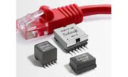
Design Support Tools Use our suite of tools to help select, analyze and compare inductors Parametric Search View our list of inductors and filter results based on your exact parameters Looking for a datasheet? Search by product and download a PDF FREE Samples Get free samples quickly - most orders ship the same day! Looking for a datasheet? Search by product and download a PDF. Student Support Learn more about magnetics, request free samples or ask our engineers a question. What is Power over Ethernet? Power over Ethernet, or PoE, is a method of delivering power to remote powered devices (PDs) using twisted–pair Ethernet cables of up to 100 meters in length. General applications include IoT, Building Automation, and Industrial Lighting. Powered devices include IP security cameras, wireless and Bluetooth access points, network routers and repeaters, VoIP phones, PDA charging systems, and LED lighting and controllers. PoE eliminates the time, expense, and required space of installing a separate line voltage power outlet, and allows for power management and control of many devices from a central location. PoE operates in the lower voltage telecom range – generally in the 36 – 57 V range, but up to 73 V – typically over category 5 (cat 5) Ethernet cables. This gives PoE a safety advantage over standard line voltage (110/220 V) power outlets. What is the PoE Standard? Requirements for PoE have been defined by the IEEE 802.3 working group as part of the 802.3 Ethernet standard. The sections particular to PoE define the physical requirements and protocols for specific data rates and various power levels over Ethernet cables. Data rates for Ethernet have evolved from the 10/100 megabits per second (Mbps) frame rates of 10/100BASE–T to the gigabits per second (Gbps) rate of 1000BASE–T Gigabit Ethernet (GigE). New IEEE 802.3 versions for PoE have been published over time to address market demands for higher power levels to be delivered to powered devices. The following shows the power delivered to the powered device (PD) for each revision: IEEE 802.3af–2003 up to 12.95 W IEEE 802.3at–2009 up to 25.5 W (2–pairs, medium power) IEEE 802.3at–2009 up to 51 W (4–pairs, high power) Power Sourcing Equipment and Powered Device Power Sourcing Equipment (PSE) – A device that provides power over the Ethernet cable to a powered device, including Endspan Equipment such as an Ethernet switch or Ethernet hub. Powered Device (PD) – The device powered by the power sourcing equipment (PSE). Midspan Equipment – A device placed between a non–PoE capable switch and a PoE PD device. Midspan Equipment How Much Power is Available? The maximum power delivered by the PSE has also evolved from a maximum of 15.40 W for IEEE 802.3af PoE up to 100 W for IEEE 802.3bt. The upcoming IEEE 802.3bt standard includes eight Classes, which describe PD power supply limits ranging from 3.84 W for Class 1 to 71.3 W for Class 8. Non-standard PoE devices may provide up to 90 W power to the powered device. What are the benefits of PoE? PoE has many advantages, including: Eliminating the need for an external wall power supply Greatly reducing installation costs Allowing flexibility in installation Powered devices can be easily moved to wherever there is a LAN cable, causing minimal disruption in the workplace The monitoring and controlling of powered devices uses the same network management infrastructure as the data transfer Shutting down or reseting devices can be done remotely, which is beneficial for Industrial / Building Automation How is power provided over Ethernet cables? There are three ways to deliver power with PoE: Through the data pair Through the spare pair How are magnetic components used in PoE? In the signal path, center-tapped 1:1 transformers are used for injecting current, and common mode chokes are used to filter out EMI. Signal path isolation transformers for both the transmit and receive sections are incorporated into a single package in Coilcraft HPX2126L Common mode chokes for both transmit and receive sections are also incorporated into a single package in Coilcraft HPF2187L This schematic shows the typical connections for PoE signal path magnetics: High Power PoE Signal Path Magnetics Pairs of these components may also be used to achieve higher (double) power levels. Coilcraft's ETH1–230L (802.3at) and ETH1–460L (802.3at) PoE Magnetics integrate signal path transformers and common mode chokes into a single package for the most compact design in applications up to 120 W. For power sourcing equipment (PSEs) or midspans, off–the–shelf magnetics are available for providing isolation, voltage transformation, and power injection. End users MUST have a transformer to provide functional isolation at the PD. Functional insulation is used to provide at least 1500 Vrms isolation between the transformer primary and secondary. Many Coilcraft off-the-shelf power transformers exist for powered devices (PDs) to provide isolation and standard voltages at a multitude of power levels. What type of PoE magnetics does Coilcraft manufacture? Coilcraft offers pre–designed off–the–shelf magnetic components for all PoE equipment types, including signal path, PSE, midspan, and PD devices from 3 W to as high as 150 W power. Visit our Power over Ethernet Magnetics page to see the breadth of our selection and the components that are listed on reference designs. Designer's Kits Copyright 2026, Coilcraft, Inc. Taiwan +886 2-2264 3646 We value your privacy We use essential and non-essential cookies on our Site, including third party advertising cookies to provide tailored ads. For more details or to manage your preferences, please see our Privacy Policy