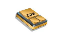
Please read the Important Notice and Warnings at the end of this document www.infineon.com/irhirel page 1 of 13 2021-09-01 IRHNJ7330SE (JANSR2N7465U3) PD-93829C Radiation Hardened Power MOSFET Surface Mount (SMD-0.5) 400V, 5.0A, N-channel, Rad Hard HEXFET™ Technology Features Single event effect (SEE) hardened Low total gate charge Proton tolerant Simple drive requirements Hermetically sealed Light weight Surface mount ESD rating: Class 1C per MIL-STD-750, Method 1020 Potential Applications DC-DC converter Motor drives Ion thrusters Product Validation Qualified to JANS screening flow according to MIL-PRF-19500 for space applications Description IR HiRel rad hard HEXFET technology provides high performance power MOSFETs for space applications. This technology has over a decade of proven performance and reliability in satellite applications. These devices have been characterized for both Total Dose and Single Event Effects (SEE). The combination of low RDS(on) and low gate charge reduces the power losses in switching applications such as DC to DC converters and motor control. These devices retain all of the well established advantages of MOSFETs such as voltage control, fast switching and temperature stability of electrical parameters. Ordering Information Table 1 Ordering options Part number Package Screening Level TID Level IRHNJ7330SE SMD-0.5 COTS 100 krad(Si) JANSR2N7465U3 SMD-0.5 JANS 100 krad(Si) Product Summary Part number: IRHNJ7330SE (JANSR2N7465U3) REF: MIL-PRF-19500/676 Radiation level: 100 krad(Si) RDS(on),max : 1.39 ID : 5.0A SMD-0.5 2 of 13 2021-09-01 IRHNJ7330SE (JANSR2N7465U3) Radiation Hardened Power MOSFET Surface Mount (SMD-0.5) Table of contents Table of contents Features ........................................................................................................................................ 1 Potential Applications ..................................................................................................................... 1 Product Validation .......................................................................................................................... 1 Description .................................................................................................................................... 1 Ordering Information ...................................................................................................................... 1 Table of contents ............................................................................................................................ 2 1 Absolute Maximum Ratings ..................................................................................................... 3 2 Device Characteristics ............................................................................................................ 4 2.1 Electrical Characteristics (Pre-Irradiation) ............................................................................................. 4 2.2 Source-Drain Diode Ratings and Characteristics (Pre-Irradiation) ....................................................... 5 2.3 Thermal Characteristics .......................................................................................................................... 5 2.4 Radiation Characteristics ........................................................................................................................ 5 2.4.1 Electrical Characteristics — Post Total Dose Irradiation .................................................................. 5 2.4.2 Single Event Effects — Safe Operating Area ...................................................................................... 6 3 Electrical Characteristics Curves (Pre-irradiation) ..................................................................... 7 4 Test Circuits (Pre-irradiation) ................................................................................................. 10 5 Package Outline .................................................................................................................... 11 Revision history............................................................................................................................. 12 3 of 13 2021-09-01 IRHNJ7330SE (JANSR2N7465U3) Radiation Hardened Power MOSFET Surface Mount (SMD-0.5) Absolute Maximum Ratings 1 Absolute Maximum Ratings Table 2 Absolute Maximum Ratings (Pre-Irradiation) 1 Repetitive Rating; Pulse width limited by maximum junction temperature. 2 VDD = 50V, starting TJ = 25°C, L = 12mH, Peak IL = 5.0A, VGS = 12V 3 ISD 5.0A, di/dt 240A/μs, VDD 400V, TJ 150°C Symbol Parameter Value Unit ID1 @ VGS = 12V, TC = 25°C Continuous Drain Current 5.0 A ID2 @ VGS = 12V, TC = 100°C Continuous Drain Current 3.2 A IDM @ TC = 25°C Pulsed Drain Current 1 20 A PD @ TC = 25°C Maximum Power Dissipation 75 W Linear Derating Factor 0.6 W/°C VGS Gate-to-Source Voltage ± 20 V EAS Single Pulse Avalanche Energy 2 150 mJ IAR Avalanche Current 1 5.0 A EAR Repetitive Avalanche Energy 1 7.5 mJ dv/dt Peak Diode Reverse Recovery 3 1.8 V/ns TJ TSTG Operating Junction and Storage Temperature Range -55 to +150 °C Lead Temperature 300 ( for 5s) Weight 1.0 (Typical) g 4 of 13 2021-09-01 IRHNJ7330SE (JANSR2N7465U3) Radiation Hardened Power MOSFET Surface Mount (SMD-0.5) Device Characteristics 2 Device Characteristics 2.1 Electrical Characteristics (Pre-Irradiation) Table 3 Static and Dynamic Electrical Characteristics @ Tj = 25°C (Unless Otherwise Specified) Symbol Parameter Min. Typ. Max. Unit Test Conditions BVDSS Drain-to-Source Breakdown Voltage 400 — — V VGS = 0V, ID = 1.0mA BVDSS/TJ Breakdown Voltage Temp. Coefficient — 0.48 — V/°C Reference to 25°C, ID = 1.0mA RDS(on) Static Drain-to-Source On-State Resistance — — 1.39 VGS = 12V, ID2 = 3.2A 1 VGS(th) Gate Threshold Voltage 2.5 — 4.5 V VDS = VGS, ID = 1mA Gfs Forward Transconductance 1.3 — — S VDS = 15V, ID2 = 3.2A 1 IDSS Zero Gate Voltage Drain Current — — 50 A VDS = 320V, VGS = 0V — — 250 VDS = 320V,VGS = 0V,TJ = 125°C IGSS Gate-to-Source Leakage Forward — — 100 nA VGS = 20V Gate-to-Source Leakage Reverse — — -100 VGS = -20V QG Total Gate Charge — — 41 nC ID1 = 5.0A VDS = 200V VGS = 12V QGS Gate-to-Source Charge — — 7.0 QGD Gate-to-Drain (‘Miller’) Charge — — 20 td(on) Turn-On Delay Time — — 25 ns ID1 = 5.0A ** VDD = 200V RG = 7.5 VGS = 12V tr Rise Time — — 75 td(off) Turn-Off Delay Time — — 58 tf Fall Time — — 58 Ls +LD Total Inductance — 4.0 — nH Measured from center of Drain pad to center of Source pad Ciss Input Capacitance — 600 — pF VGS = 0V VDS = 25V ƒ = 1.0MHz Coss Output Capacitance — 165 — Crss Reverse Transfer Capacitance — 60 — ** Switching speed maximum limits are based on manufacturing test equipment and capability. 1 Pulse width 300 μs; Duty Cycle 2% 5 of 13 2021-09-01 IRHNJ7330SE (JANSR2N7465U3) Radiation Hardened Power MOSFET Surface Mount (SMD-0.5) Device Characteristics 2.2 Source-Drain Diode Ratings and Characteristics (Pre-Irradiation) Table 4 Source-Drain Diode Characteristics Symbol Parameter Min. Typ. Max. Unit Test Conditions IS Continuous Source Current (Body Diode) — — 5.0 A ISM Pulsed Source Current (Body Diode) 1 — — 20 A VSD Diode Forward Voltage — — 1.2 V TJ = 25°C, IS = 5.0A, VGS = 0V 2 trr Reverse Recovery Time — — 516 ns TJ = 25°C, IF = 5.0A, VDD ≤ 50V di/dt = 100A/μs 2 Qrr Reverse Recovery Charge — — 3.8 μC ton Forward Turn-On Time Intrinsic turn-on time is negligible (turn-on is dominated by LS+LD) 2.3 Thermal Characteristics Table 5 Thermal Resistance Symbol Parameter Min. Typ. Max. Unit RJC Junction-to-Case — — 1.67 °C/W RJ-PCB Junction-to-PC board (soldered to a 2” square copper-clad board) — 6.9 — 2.4 Radiation Characteristics IR HiRel Radiation Hardened MOSFETs are tested to verify their radiation hardness capability. The hardness assurance program at IR HiRel is comprised of two radiation environments. Every manufacturing lot is tested for total ionizing dose (per notes 3 and 4) using the TO-3 package. Both pre- and post-irradiation performance are tested and specified using the same drive circuitry and test conditions in order to provide a direct comparison. 2.4.1 Electrical Characteristics — Post Total Dose Irradiation Table 6 Electrical Characteristics @ TJ = 25°C, Post Total Dose Irradiation 3, 4 Symbol Parameter 100krad (Si) Unit Test Conditions Min. Max. BVDSS Drain-to-Source Breakdown Voltage 400 — V VGS = 0V, ID = 1.0mA VGS(th) Gate Threshold Voltage 2.0 4.5 V VDS = VGS, ID = 1.0mA IGSS Gate-to-Source Leakage Forward — 100 nA VGS = 20V Gate-to-Source Leakage Reverse — -100 VGS = -20V IDSS Zero Gate Voltage Drain Current — 50 μA VDS = 320V, VGS = 0V RDS(on) Static Drain-to-Source On-State Resistance (TO-3) 2 — 1.39 VGS = 12V, ID2 = 3.2A RDS(on) Static Drain-to-Source On-State Resistance (SMD-0.5) 2 — 1.39 VGS = 12V, ID2 = 3.2A VSD Diode Forward Voltage — 1.2 V VGS = 0V, IF = 5.0A 1 Repetitive Rating; Pulse width limited by maximum junction temperature. 2 Pulse width 300 μs; Duty Cycle 2% 3 Total Dose Irradiation with VGS Bias. VGS = 12V applied and VDS = 0 during irradiation per MIL-STD-750, Method 1019, condition A. 4 Total Dose Irradiation with VDS Bias. VDS = 320V applied and VGS = 0 during irradiation per MlL-STD-750, Method 1019, condition A. 6 of 13 2021-09-01 IRHNJ7330SE (JANSR2N7465U3) Radiation Hardened Power MOSFET Surface Mount (SMD-0.5) Device Characteristics 2.4.2 Single Event Effects — Safe Operating Area IR HiRel radiation hardened MOSFETs have been characterized in heavy ion environment for Single Event Effects (SEE). Single Event Effects characterization is illustrated in Fig. 1 and Table 7. Table 7 Typical Single Event Effects Safe Operating Area Ion LET (MeV/(mg/cm2)) Energy (MeV) Range (μm) VDS (V) VGS = 0V VGS = -5V VGS = -10V VGS = -15V Cu 28 285 43 325 325 325 325 Br 36.8 305 39 325 325 325 275 Figure 1 Typical Single Event Effect, Safe Operating Area 7 of 13 2021-09-01 IRHNJ7330SE (JANSR2N7465U3) Radiation Hardened Power MOSFET Surface Mount (SMD-0.5) Electrical Characteristics Curves (Pre-irradiation) 3 Electrical Characteristics Curves (Pre-irradiation) Figure 2 Typical Output Characteristics Figure 3 Typical Output Characteristics Figure 4 Typical Transfer Characteristics Figure 5 Normalized On-Resistance Vs. Temperature 8 of 13 2021-09-01 IRHNJ7330SE (JANSR2N7465U3) Radiation Hardened Power MOSFET Surface Mount (SMD-0.5) Electrical Characteristics Curves (Pre-irradiation) Figure 6 Typical Capacitance Vs. Drain-to-Source Voltage Figure 7 Gate-to-Source Voltage Vs. Typical Gate Charge Figure 8 Typical Source-Drain Current Vs. Diode Forward Voltage Figure 9 Maximum Safe Operating Area 9 of 13 2021-09-01 IRHNJ7330SE (JANSR2N7465U3) Radiation Hardened Power MOSFET Surface Mount (SMD-0.5) Electrical Characteristics Curves (Pre-irradiation) Figure 10 Maximum Drain Current Vs.Case Temperature Figure 11 Maximum Avalanche Energy Vs. Junction Temperature Figure 12 Maximum Effective Transient Thermal Impedance, Junction-to-Case 10 of 13 2021-09-01 IRHNJ7330SE (JANSR2N7465U3) Radiation Hardened Power MOSFET Surface Mount (SMD-0.5) Test Circuits (Pre-irradiation) 4 Test Circuits (Pre-irradiation) Figure 13 Gate Charge Test Circuit Figure 14 Gate Charge Waveform Figure 15 Unclamped Inductive Test Circuit Figure 16 Unclamped Inductive Waveform Figure 17 Switching Time Test Circuit Figure 18 Switching Time Waveforms 11 of 13 2021-09-01 IRHNJ7330SE (JANSR2N7465U3) Radiation Hardened Power MOSFET Surface Mount (SMD-0.5) Package Outline 5 Package Outline Note: For the most updated package outline, please see the website: SMD-0.5 12 of 13 2021-09-01 IRHNJ7330SE (JANSR2N7465U3) Radiation Hardened Power MOSFET Surface Mount (SMD-0.5) Revision history Revision history Document version Date of release Description of changes 08/04/2000 Datasheet (PD-93829) Rev A 01/28/2003 Updated based on Switch time test condition Rev B 02/07/2003 Updated TO-3 package Rdson from 1.41Ohm to 1.39Ohm Rev C 09/01/2021 Updated based on ECN-1120_08758 Edition 2021-09-01 Published by International Rectifier HiRel Products, Inc. An Infineon Technologies company El Segundo, California 90245 USA © 2021 Infineon Technologies AG. All Rights Reserved. Do you have a question about this document? Email: [email protected] Document reference IMPORTANT NOTICE The information given in this document shall in no event be regarded as a guarantee of conditions or characteristics (“Beschaffenheitsgarantie”). With respect to any examples, hints or any typical values stated herein and/or any information regarding the application of the product, Infineon Technologies hereby disclaims any and all warranties and liabilities of any kind, including without limitation warranties of non-infringement of intellectual property rights of any third party. In addition, any information given in this document is subject to customer’s compliance with its obligations stated in this document and any applicable legal requirements, norms and standards concerning customer’s products and any use of the product of Infineon Technologies in customer’s applications. The data contained in this document is exclusively intended for technically trained staff. It is the responsibility of customer’s technical departments to evaluate the suitability of the product for the intended application and the completeness of the product information given in this document with respect to such application. For further information on the product, technology, delivery terms and conditions and prices please contact your nearest Infineon Technologies office (www.infineon.com). WARNINGS Due to technical requirements components may contain dangerous substances. For information on the types in question please contact your nearest International Rectifier HiRel Products, Inc., an Infineon Technologies company, office. International Rectifier HiRel Components may only be used in life-support devices or systems with the expressed written approval of International Rectifier HiRel Products, Inc., an Infineon Technologies company, if failure of such components can reasonably be expected to cause the failure of that life-support device or system, or to affect the safety and effectiveness of that device or system. Technologies, Infineon Technologies’ products may not be used in any applications where a failure of the product or any consequences of the use thereof can reasonably be expected to result in personal injury. Life support devices or systems are intended to be implanted in the human body, or to support and/or maintain and sustain and/or protect human life. If they fail, it is reasonable to assume that the health of the user or other persons may be endangered. Trademarks All referenced product or service names and trademarks are the property of their respective owners.