In the world of power electronics, most instrumentation-grade devices contain a source function and a measurement function. A high-performance power supply is a one-box solution that includes the voltage source, current source, voltmeter, and ammeter. A battery tester contains a charger (source), a discharger (load), a voltmeter to measure battery voltage, and an ammeter to measure battery current.
These power electronics are used for critical applications where control must be carefully maintained, such as to ensure a charger doesn’t overcharge a battery or that the power supply doesn’t damage a sensitive device under test. Furthermore, these power electronics are used where accurate measurement is needed, such as to report on the measured capacity of a battery or measure the dynamic current being drawn by a device as it operates in various states.
If careful control of a source and accurate measurement is needed, then these power electronics must be calibrated. Even if the power instrument was in perfect calibration when it left the factory, components inside will drift over time due to many factors, including mechanical shock (like dropping the instrument) or heat cycling (as the instrument heats up and cools down during normal operation). The purpose of performing calibration at set intervals is to ensure the power instrument returns to its best calibrated state before it drifts out of calibration.
In the old days, calibration was a mechanical process. Power instruments contained many potentiometers that needed adjustment to bring the power instrument back into calibration. In the modern world, power-instrument manufacturers use electronic calibration. With electronic calibration, there’s no need to open the instrument and adjust. The calibration can be done without moving the instrument, so if it’s in a rack of test equipment or built into a test station, you needn’t tear apart the system.
Calibrating Power Sources
Let’s look first at power sources. So, what happens if you have a voltage source that’s not calibrated and you try to use it to output a voltage, P1? You program the voltage source to generate voltage P1, but the voltage source isn’t calibrated. As a result, the voltage source doesn’t generate voltage P1, as desired. Instead, the voltage source generates voltage A1, which is not what you wanted. Therefore, you must calibrate the voltage source if you want it to properly generate voltage P1.
So, what’s happening inside the voltage source when it’s asked to generate P1 but instead generates A1? Here’s the internal programming process:
- The desired source voltage output is P1.
- Internally, the voltage source programs a digital-to-analog converter (DAC) using value D1 to program the output to P1.
- But when the DAC is programmed using D1, the source generates A1, an incorrect voltage, because the source is not calibrated.
Now, we can calibrate the voltage source to correct for this:
- Using external DMM, we can measure the difference between P1 (expected voltage) and A1 (actual voltage).
- The difference (P1 - A1) is an error that we can calibrate out using an adjustment factor.
- We can create an adjustment factor α to set DAC to (D1+α) such that when the adjustment factor is applied, the voltage source will be calibrated.
- The calibrated voltage source instead uses DAC value (D1+α), which results in output P1, thanks to the calibrated output.
During the calibration process, we find out how far off the source is from the desired value by measuring the actual source output voltage and then calculating a set of adjustment factors to bring the output into calibration. To measure the actual source output voltage, use a calibrated digital multimeter (DMM). The DMM must be significantly more accurate than the expected accuracy of the voltage source. Normally, the performance of the DMM needs to be 10X better than the voltage source, but 4X better is marginally acceptable.
To determine the adjustment factor for the full range of the voltage source output, you set the voltage to a low point in the voltage-source operating range, then measure the actual low point value generated by the voltage source. Next, you set the voltage to a high point near the full-scale output in the voltage-source operating range, then measure the actual high point value generated by the voltage source.
Most voltage source circuits will behave linearly, so the two points, low and high, can be used to determine a slope (gain) and offset using the correction formula Y = m X + b, where m = gain and b = offset. By applying this gain and offset to each programmed voltage, it’s possible to bring the output back into correction and achieve calibration.
Real-World Example
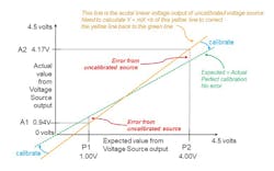
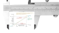
Let’s look at a real example for a voltage source that can produce 0 to 5 V (see figure):
- Connect a calibrated DMM to the output of the uncalibrated voltage source.
- Set uncalibrated voltage source to output P1 = 1.0 V.
- Use DMM to measure actual output voltage A1. DMM measures 0.94 V.
- Set uncalibrated voltage source to output P2 = 4.0 V.
- Use DMM to measure actual output voltage A2. DMM measures 4.17 V.
- As shown in the table, calculate Y = m X + B where m = GAIN, B = OFFSET.
- Store those adjustment factors in non-volatile RAM so that they can be used throughout the calibration cycle until the next time the voltage source is calibrated.
- Apply GAIN and OFFSET to create new DAC values that will give the corrected, calibrated output.
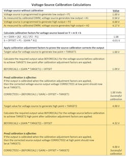
To summarize how to apply calibration adjustment factors:
- You want the voltage source to generate voltage V.
- You will need to set the output to BEFORECAL, where BEFORECAL = (GAIN * V) – OFFSET.
- When you program the voltage source to BEFORECAL, you will get V from the voltage source.
Calibrating Current and Measurement Input
While this article has covered calibration of a voltage source, the calibration for a current source is the same, except you would compare expected current vs. actual output current. For a current-source calibration, an electronic load would be needed to draw the current from the power source. You would also need a high-performance ammeter or an accurate current transducer and a high-performance voltmeter to measure the transducer’s output.
Lastly, this same process can be used to calibrate a measurement input. In this case, an external calibrated voltage would be applied to the measurement input. Then, the uncalibrated measurement from the measurement input would be compared to the known value of the calibrated voltage source. The adjustment factors of gain and offset are calculated (from Y = m X + b) and applied to correct for the error in the measurement.
About the Author

Bob Zollo
Solution Architect for Battery Testing, Electronic Industrial Solutions Group
Bob Zollo is solution architect for battery testing for energy and automotive solutions in the Electronic Industrial Solutions Group of Keysight Technologies. Bob has been with Keysight since 1984 and holds a degree in electrical engineering from Stevens Institute of Technology, Hoboken, N.J. He can be contacted at [email protected].
Comment About the Article
To join the conversation, and become an exclusive member of Electronic Design, create an account today!

Leaders relevant to this article: