Synthesized Inductor Delivers Maximum Power Transfer

>> Electronic Design Resources
.. >> Library: Article Series
.. .. >> Series: Ideas for Design
.. .. .. >> Ideas for Design Vol. 1
Download this article as a PDF file
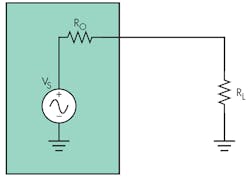
To transfer maximum power from a circuit to a load, the load’s resistance, RL, must match the source resistance, Ro (Fig. 1). In the case of a complex load, ZL, and a resistive source, this transfer can require the use of a bulky inductor. This idea shows how to replace the physical inductor with a smaller synthesized inductor.
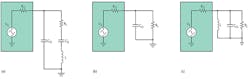
A good example of a complex load is a piezoelectric transducer represented by the Butterworth-Van Dyke model as Co, RL, Cs, and L (Fig. 2a). At series resonance, the load impedance reduces to the equivalent circuit shown in Figure 2b. The load is still complex, with RL in parallel with Co. This makes matching to Ro impossible without a complex conjugate match of –Co at the source—that is, an inductor in parallel with Co and having the same magnitude of reactance (Fig. 2c).
To match Ro to RL, L must be chosen to “resonate out” Co:
–XCo = XL
– {–j[1/(ωCo)]} = jωL
Therefore:
L = 1/(ω2 × Co)
where:
ω = 2πf
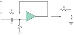
To replace the physical inductor, L, with a synthesized inductor, consider the gyrator circuit, which Bernard Tellegen invented in 1948 (Fig. 3). The circuit is basically a differentiator in which the operation of capacitor C is reversed. The simulated inductance becomes:
L = (R1)(R)(C) Henries
Typically, R1 is kept to 100 Ω or less so the circuit’s Q can be at least 10. (Details of the gyrator circuit are available on the Internet. For example, see www.beigebag.com/case_gyrator.htm. Figure 4 shows the final implementation of the matched circuit. With this circuit, R can be dynamically varied to change the tuning on the fly for different complex loads, provided that the voltage across the load is measured so optimum tuning can be achieved.
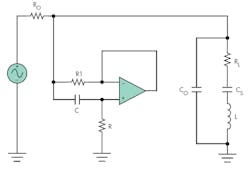
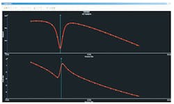
Figure 5 shows the simulation results of a tuned circuit using the described gyrator circuit. The top trace is the voltage across the load, which shows a minima at the resonant frequency. The bottom trace shows the phase of the voltage across the load, which is 0° at resonance. These results indicate that the selected synthesized inductance successfully matches the load to the source.

About the Author
Comment About the Article
To join the conversation, and become an exclusive member of Electronic Design, create an account today!

Leaders relevant to this article: