Stabilize SMPS With Slope Compensation Resistance

>> Electronic Design Resources
.. >> Library: Article Series
.. .. >> Series: Ideas for Design
.. .. .. >> Ideas for Design Vol. 1
Download this article as a PDF file
Current-control switching-mode power supplies (SMPS) are gaining in popularity because they allow pulse-by-pulse current control and monitoring, making them more reliable and robust than their voltage-controlled counterparts. Current control also eliminates a positive zero in some transfer functions, which makes the supplies more stable. However, at pulse duty cycles above 0.5, current-control SMPS become unstable, oscillating at half of the switching frequency.1
To stabilize the circuit, the designer must change the slope of the pulses going to the pulse-width modulation (PWM) comparator.2 This can be done by adding a sawtooth voltage derived from the voltage across the timing capacitor to the voltage developed across the current-sensing resistor. Or, you can add a high-enough current slope to the slope-shaping resistor before summing the voltage across the slope-shaping resistor and the current-sensing resistor in the current-sensing transformer’s output circuit.
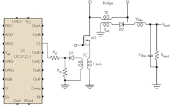
This idea describes how to compute the value of the slope compensation resistor, Rsl, that will create the desired voltage pulse slope. The analysis uses Figure 1, which is part of a bridge converter that is a component of a current-control SMPS. Although the figure is a simplified schematic that denotes rectifiers as diodes and does not show the full bridge, it is suitable for this analysis.
Related Articles
• Constant-Current Source Creates Slope-Compensation Ramp In SMPS
• Buck Converter Powers 5-V Circuits From 12-V Solar-Cell Array
• Constant-Current Source Creates Slope-Compensation Ramp in SMPS
The voltage pulse slope is sent to the current-sensing input of U1, an LTC3722-1 synchronous dual-mode phase-modulated full-bridge controller with an internal current-ramping source whose peak current reaches 74 µA. This internally generated current creates the compensation slope that adds to the slope of a pulse that is developed across the current sensing resistor, Rcs, making the current feedback loop stable at any duty cycle.
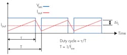
The computation starts with the known factors: the SMPS output power, voltage, switching frequency, and other parameters that are obtained during the power supply analysis. Assuming that the pulses across the secondary winding of transformer TR have an amplitude of Vsec, and neglecting the voltage drop across rectifier D2, which may be a synchronous low-dropout type:
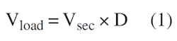
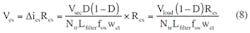
where D is the duty cycle of the rectified pulses. Note that Vload is not the rms value of Vsec. Then, the current ripple in the filter inductor, ∆iL, is:
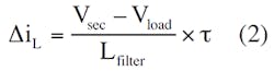
where Lfilter is the value of the filter inductance and τ is the duration of the output pulse. Substituting Equation 1 into Equation 2:
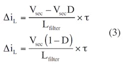
with a switching frequency of fsw and τ = D/fsw:
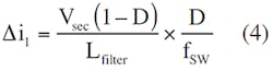
with a transformation coefficient or windings turn ratio of Ntr for TR of:
Ntr = w2/wl
and a MOSFET source current of:
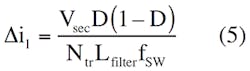
∆il = ∆iL/Ntr
Equation 4 becomes:
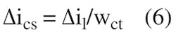
Assuming that the current transformer, TC, has one turn on the primary side and wct turns on the secondary, and the current-sensing resistor current is ∆ics:
Substituting Equation 5 into Equation 6:
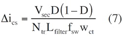
Then, the voltage across Rcs is:
The voltage slope, Slopesl, created by U1’s internal current generator, Isl, or by an external component is:
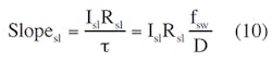
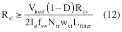
Equation 10 ignores the value of Rcs, which is much smaller than Rsl. Slopesl should be equal to or greater than 0.5 Slopecs. So:
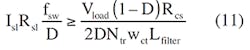
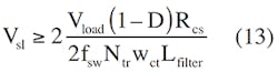
Then:
and:
The value of Rcs is obtained by using the ratio of U1’s sensing voltage to the operating current, scaled by the current transformer.
Sometimes, however, the IC’s current-sensing input has a current-limiting threshold, Vth. If needed to avoid reaching the current-limiting mode, Rcs may be calculated using:
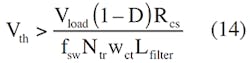
Now you can calculate the Rcs value that will ensure smooth operation of the power supply in the normal mode:
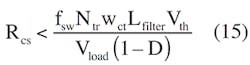
After making this calculation and selecting a standard value, you can use that value in Equation 12 to compute Rsl.
If the controller IC that you employ does not provide the required current sawtoooth waveform, you can derive it from the voltage across the timing capacitor. Just add a simple power amplifier based on two complementary bipolar transistors.
References
About the Author
Gregory Mirsky
Princpal Electrical Engineer
Gregory Mirsky is a principal electrical engineer at Atlas Materials Testing Company (an Ametek Company). He holds an MS from the St. Petersburg Baltic Technical University, Russia, and a PhD from the Moscow State Pedagogical University.
Comment About the Article
To join the conversation, and become an exclusive member of Electronic Design, create an account today!

Leaders relevant to this article: