Thousands of ready-made off-the-shelf transformers out in the market are available to be designed into electronic or electrical circuits. However, when the right part just can’t be found, you may want to consider designing a custom transformer to fit your specific requirements.
This file type includes high resolution graphics and schematics when applicable.
You need to determine a few things before you can start to design a transformer, though. At the minimum, these include the input voltage(s) and frequency, and the output voltage(s) and current(s). There may very well be other parameters to consider, both physical and electrical, such as available space for mounting, mounting style, isolation requirements, leakage currents, etc. Environmental conditions may also be a consideration.
Note: At this step, it’s important to point out that all of the decisions made concerning the design will be verified through calculations that can only be made after many “rules of thumbs’” and “educated guesses” are used to get us to that point.
Selecting the Core
The first step is to determine the type of core for the design. You should consult with a core manufacturer to obtain the specific characteristics and power-handling capabilities for each type and size of core. However, a general starting point is:
• When less than 400 Hz, a silicon steel lamination is generally used.
• At 400 to 2000 Hz, consider a tape-wound or nickel-alloy core.
• Above 2000 Hz, look at ferrite.
Remember this is only a guideline; it’s not uncommon to go outside of these ranges (e.g., audio transformers can use silicon steel laminations and operate from 20 to 20,000 Hz). There are many other core types, and many sizes, shapes, and material grades within the cores listed above. The exact core chosen may depend on board spacing, location, mounting style, or any of a number of physical and electrical parameters that only you can decide.
Most core types will also need a winding bobbin to fit the core that you choose, and possibly assist in the mounting of the finished product. Make sure a sufficient bobbin style and material is available, and that you have all of the mechanical measurements to determine winding details later on in the design. Certain cores don’t require a bobbin, but we’ll save those for another discussion.
After selecting a core and bobbin, you need to calculate the correct number of primary turns needed using formula 1 or 2 (see “Basic Design Formulas,” below). There are several variables to consider when using these formulas; you will need to consult the core manufacturer’s data for answers to specifications such as flux density and stacking factor.
Basic Design Formulas
1) N(p) = (V x 108) / (4.44 B A f K) sine wave
2) N(p) = (V x 108) / (4 B A f K) square wave
3) N(s) = V(s) / V(p) x N(p)
4) I(p) = (VA(s) + losses) / V(p)
5) I(s) = P(out) / V(out)
6) Open circuit voltage (Voc) = N(s)/N(p) x V(p)
7) Loaded voltage (Vld) = Voc-[IR(sec) + (IR(pri) x (N(s)/N(p))]
8) Temp rise (T(C)) = (losses/(0.008 x surface area))
N(p) = Primary turns
N(s) = Secondary turns
B = Flux density in gauss
A = Core area in centimeters squared
f = Frequency
K = Stacking factor
L = Inductance
A(l) = Inductance per turn squared for a given core
Windings and Wire
The primary winding current and wire size needs to be determined. The primary current will be equal to the total output power plus transformer power losses, divided by the primary voltage. For power losses, I start at a 10% increase in the input power, assuming a 90% efficient transformer. For example, a transformer with a 12-V, 2-A output at 120 V input would be:
12 V x 2 A = 24 VA; 24 VA x 1.10 (110%) = 26.4 VA needed in the primary winding;
26.4 VA/120 V = 0.22 A in the primary winding
The next step will be a subject for debate and adjustment depending on the transformer characteristics: I generally start at approximately 500 circular mills (cm) per amp to choose the starting wire gauge. This number may be smaller for small transformers, and larger for large power transformers; that decision is again up to the designer. Using the example above, 0.22 A x 500cm/A = 110cm; I would start with a 29 gauge wire (127.7cm) for the primary.
You now need to determine the number of turns that will be required for each secondary winding. The first step is to use formula 3 (N(s) = V(s) / V(p) x N(p)) to determine the turns for a perfect transformer. This number then needs to be increased to account for the losses in the coils. As a rule of thumb again, I start with a 10% increase in the number of turns, assuming a 90% efficient transformer: N(s) x 1.10 = N Turns. This percentage will vary depending on the characteristics of your design. Use the same method to determine the secondary wire gauge(s) that you used for the primary.
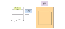
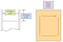
Now you need to see if the windings fit into your winding area and determine the actual losses of the coils. Start by determining the winding width (ww) of the bobbin, the winding height (wh) of the bobbin, and the mean length of turns (mlt) from the mechanical drawing (see the figure).
With this information, you can now calculate how many turns of wire can fit in each layer of winding for each different winding. After that, determine how many layers of each wire gauge used it will take to wind the calculated number of turns for each given winding. Finally, calculate the total height of all of the windings wound concentrically. Remember to include the insulation used between the windings in figuring your total winding height.
Verification
The next step is to verify your design. Will it fit in the allowable winding height with enough “play” to allow for error? Keep in mind that the windings will not be perfectly layered, so you must allow for some bowing of the copper wire as it bends around each corner of the bobbin. I use a maximum of 85% fill (or build) when comparing the actual winding height to the allowable bobbin winding height:
(Actual winding height/Allowable winding height) × 100 = < 85%
A build of around 75% is more desirable, and will make the transformer easier to manufacture in the long run.
Next, you need to calculate the resistance of each winding, and the loaded voltage losses in the winding to determine loaded output voltages. First, the resistance of each winding is calculated by multiplying the mean length of turn by the number of turns. This gives the total length of the wire conductor. Whatever unit of measure you are using, convert this length to thousands of feet (K ft); for example, a length of 400 in./12000 = 0.03 K ft. Now from a magnet wire chart, you can get resistance of each gauge of wire in thousands of feet. For our example, 29 gauge has a resistance of 81.21 Ω/K ft, so a 400-in. wire would have a resistance of 0.03 K ft × 81.21 Ω /K ft = 2.44 Ω.
Once you have the resistance of a winding, you simply calculate the voltage drop across that winding by multiplying the resistance by the current in the winding. In this primary it would be 2.44 Ω x 0.22 A = 0.540 V. Calculate the voltage drop across each winding in the same manner.
The next step is to calculate the open-circuit voltage of each secondary using formula 6 and the loaded voltage using formula 7 of (see “Basic Design Formulas”). I put these together because I usually do both calculations on each secondary winding before moving on to multiple windings if I have them.
The key thing to note here is that the primary voltage drop is reflected into the secondary loaded voltage by the ratio of the turns. After that, it’s added to the secondary voltage drop. The sum of the two is then subtracted from the open circuit voltage of the given secondary. This gives you the loaded output voltage of that secondary (I realize the formula could be mathematically simplified, but this format allows me easier use with a calculator; again, my opinion).
If the voltage is not what you want, divide the desired output voltage by the calculated output for an error ratio. Use this ratio multiplied by the number of turns on the given secondary and recalculate everything starting at the number of layers of winding.
Temp Calculations
After calculating the turns, you need to know the calculated temperature rise. There are two main causes of temperature rise in a transformer: core power losses and winding power losses. To determine the core power losses, refer to manufacturer’s datasheets and the flux density used in your design. Winding power losses are easily calculated by multiplying the voltage drop across the winding again by the current in the winding (I2R). The sum of the power losses in the windings, primary(s), and secondary(s) is multiplied by 1.33 (I’ll be honest, I don’t fully know where this factor came from, but it has to do with heat transfer and concentric windings, and it works) to give the total effective heating losses of the windings. Add the core losses to the winding losses for total power dissipation.
To determine how well the transformer dissipates power losses, we need to calculate the surface area of the completed device. This simply requires looking at all of the surfaces that will be exposed to air and adding them up in inches squared. Now use formula 8 from the design formulas to calculate the estimated temperature rise of the transformer.
This file type includes high resolution graphics and schematics when applicable.
Once again, what constitutes an acceptable temperature rise depends on the application and the designer. I always use 50ºC as my maximum rise allowed. Keep in mind that forced air cooling or heat sinks may be used in the end product, which could push that number higher.
Now that you’ve made all of your decisions on the design aspects, based on “rules of thumb” and “educated guesses,” you should be able to confirm the choices made using the formulas and calculations discussed in the article. If things anywhere along the way don’t work, you have to go back, make the appropriate changes, and start over. This includes the temperature-rise calculation.
About the Author
Eric Christensen
Director of Engineering and Sales
Eric Christensen, sole proprietor of ARA Enterprises LLC, a consulting company that contracts to Magnelab Inc. as director of engineering and sales, has over 20 years of custom magnetics design and manufacturing experience in the medical, military, and aerospace industries, among others. He holds a BSEET degree from Colorado Technical University, Colorado Springs.
Comment About the Article
To join the conversation, and become an exclusive member of Electronic Design, create an account today!

Leaders relevant to this article: