Current Limiter Offers Circuit Protection with Low Voltage Drop
Download this article in .PDF format
There are many cases where a power supply needs an internal current-limiter function, usually built using a current sensor, a control circuit, and a pass transistor. The current sensor itself can be a simple low-value resistor; since the voltage across it is proportional to the current, this voltage can be used to control the current flow through the pass transistor.
In one example of this configuration (Fig. 1), RSENSE is a low-value resistor used for sensing the current.1 As long as the voltage across this resistor is less than 0.6 V or so, only transistor T1 will conduct. Whenever load current IL reaches a value such that when RSENSE voltage (equal to IL × RSENSE) exceeds approximately 0.6 V, transistor T2 starts conducting. The base current of T1 is drawn by T2 and, as a consequence, the emitter current of T1 drops.
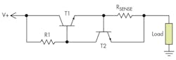
Figure 1. A simple, widely used current limiter consists of a current sensor (usually a low-value sense resistor), a control circuit, and a pass transistor.
However, this simple circuit has a limitation due to the associated voltage drop; when activated, there will be a voltage drop at T1 (VCE,SAT) of ~1 V and across RSENSE of ~0.6 V. The total voltage drop is ~1.6 V. Therefore, if the current limiter is connected with a +5-V supply, the load will get ~3.4 V, which is unacceptable in low-voltage circuits.
An alternative is to use the well-known LM317 voltage regulator as a current limiter.2 This approach also incurs a voltage drop of ~ 2 V. Another current limiter uses a P-channel MOSFET as a pass device, with gate voltage controlled by a transistor that amplifies the RSENSE voltage drop.3 This circuit experiences a drop as low as ~0.6 V.
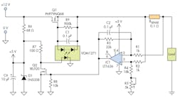
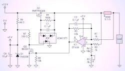
Figure 2. This more complicated current limiter has the advantage of much-lower voltage drop than the previous design, which is a critical factor in circuits operating from low-value supplies.
The current limiter of Figure 2 has very low voltage drop, so it doesn’t hamper low-voltage circuit operation. The circuit operates from minimum supply voltage of 5 V, to higher values set by some components. The voltage across the 0.1-Ω sense resistor is amplified by op-amp IC1 in differential mode; IC1's +5-V supply comes from D1, a Zener-diode acting as a regulator.
For adjustable current limit, the gain of the op amp is controlled by the variable resistor R5. The output of IC1 controls the drain-source resistance (RDS) of low-threshold MOSFET Q2, and the drain current of Q2 controls the LED current of VOM1271, a photovoltaic MOSFET driver.4
When the load current is low, the RSENSE voltage is low, and the low IC1 output remains below the threshold of Q2. The resultant higher LED current of the MOSFET driver produces an output voltage of ~8 V, which is high enough to drive Q1 well into full conduction. When the load current reaches a value that drives Q2 into conduction, gate-source voltage VGS of Q1 goes low, which forces the load current to go low.
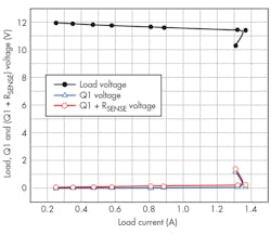
Figure 3. Variation of load, Q1, and Q1+RSENSE voltages versus a range of load-current values shows relative flatness.
The circuit was tested with a +12-V supply and a 100-Ω high-power variable resistor as a load. Potentiometer R5 was adjusted to set the current limit a little above 1 A. The load resistor was slowly reduced from its maximum value, and voltages across Q1, RSENSE, and the load were measured (Fig. 3). For load current from 0.25 to 1.3 A, the voltage drops across Q1 and Q1 + RSENSE were 0.09 V and 0.235 V, respectively.
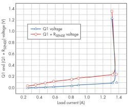
Figure 4. The expanded view of Q1 and Q1+RSENSE voltages more clearly shows the current-limiting foldback action that occurs when the load current exceeds the set limit.
At the maximum load current of 1.3 A, the voltage drop across RSENSE of 0.145 V is a significant contributor to the overall drop. The drop can be reduced further by choosing lower values of RSENSE. The expanded view of the voltage drops at Q1 and Q1+RSENSE(Fig. 4) shows how these two drops vary with load current. When the load current exceeds the set limit, it triggers a current-limiting foldback action.
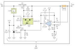
Figure 5. Despite its internal complexity, the entire current-limiter circuit can be considered as a three-terminal device.
This current limiter is suitable for low-voltage applications beginning at +5 V. For higher voltages or operation in a wider voltage range, Zener biasing resistor R6 can be replaced with a constant-current regulator (CCR), and Q1 should be chosen for higher voltage or current rating. The entire current-limiter circuit can be packaged and used as a three-terminal device (Fig. 5).
Sajjad Haidar is an Electronics Technologist at the Electronics Engineering Services of the University of British Columbia (UBC). He holds an M.Sc. in applied physics and electronics from the University of Dhaka (Bangladesh). Previously, he worked in Japan for seven years in the field of tunable solid-state lasers and optoelectronics. He can be reached at [email protected].
References:
1. https://en.wikipedia.org/wiki/Current_limiting
2. http://www.ti.com/lit/ds/symlink/lm317.pdf
3. http://www.electro-tech-online.com/articles/adjustable-low-drop-current-limiter.660
About the Author
Comment About the Article
To join the conversation, and become an exclusive member of Electronic Design, create an account today!

Leaders relevant to this article: