Componentized Direct-Drive Electric Generator Targets New and Refurbished Wind Turbines
Download this article in PDF format.
Wind turbines larger than 6 MW are becoming common, particularly for offshore installations, where consolidating several smaller wind turbines into one large version reduces manufacturing, installation, and sustainment costs in accordance with economies of scale.
The overall reliability of the wind turbine is mostly determined by the mechanical gearbox, which converts the practical low speed of the wind-turbine rotor propeller hub (e.g., 5 to 20 RPM) to the variable high speed of a conventional electric generator system (e.g., two pole-pair, 60 Hz, 450 to 1800 RPM). In turn, large wind turbines are eliminating the gearbox (and its compounded inefficiency, complexity, size, and cost) with low-speed, directly driven electric generator systems. However, as physics dictates, low-speed electric generator systems are necessarily large in diameter (and heavy).
For example, the radial-flux, direct-drive, rare-earth permanent-magnet (RE-PM) electric generator of the 12-MW Haliade-X wind turbine from GE is approximately 11 meters (or 36 ft) in diameter and consumes a significant portion of the 20.6-meter (67.5 ft) long nacelle weight, which is over 600 metric tons (or 660 tons). All of that must be transported to the wind-turbine installation site over specially prepare routes and then lifted more than 130 meters to the tower hub. Accordingly, the manufacture, installation, maintenance, and transportation of large wind-turbine generator systems requires uncommonly large, specialized, and expensive handling equipment with complicated transportation logistics.
The Call for Lightweight, Low-Speed Wind Turbines
Under an ARPA-E program, the U.S. Department of Energy is asking for a “lightweight” (or small) high-power, low-speed (e.g., 5 to 20 RPM), direct-drive electric generator system for the next generation of large wind turbines. But a “lightweight” direct-drive electric generator seemingly contradicts standard electric motor or generator (i.e., electric machine) design principles and trade space as follows:
- Increasing electric-machine air-gap flux density reduces the effective air-gap area with associated reduction of physical size, amount of copper magnet wire, and amount of electrical steel for a given power rating (all in accordance to Faraday’s Law). However, air-gap flux density (and associated effective air-gap area) will be similar among all optimally designed, conventional electric machines due to the flux-density saturation limit of the same slotted electrical steel core and material equally used by all. It’s not impacted by the limited residual flux density potential of the RE-PM as commonly suggested (that ideally shows no electrical dissipation but adversely trades residual flux density, β, for coercivity or flux intensity, H, in accordance with the fixed RE-PM energy product or BHmax), nor by the even higher flux-density potential of winding magnetizing magneto-motive-force (MMF) (that adversely shows electrical dissipation but ideally increases flux density directly with higher flux intensity).
- Although very low excitation frequency provides the best means of reducing pole-pair count (and associated electric machine diameter), all optimally designed, low-speed, direct-drive generators still have comparably large diameters (and physical sizes). That’s due to the limited low-frequency performance of today’s electronic control, which still necessitates a large number of pole-pairs and associated slots (or coreless framework) along the air-gap circumference for the placement and structural support of at least the necessary conventional “active” winding set. It may be sinusoidally distributed (most efficient) or segmented/concentrated (least efficient), or have extraneous “passive” RE-PMs, dc electromagnets, reluctance saliencies, or slip-induction windings (with the slot dimension determined by the wire gauge or RE-PM size to meet the power rating).
- Direct-current superconducting electromagnets (sometimes called super permanent magnets) produce at least double the air-gap flux density than what’s practical with conventional magnetizing MMF and without regard to the flux-density saturation limits of the electrical steel core. However, the diameter of a low-speed superconducting electric-machine system still depends on the accumulation of slots (or framework) along the airgap circumference (for at least the structural support of the necessary “conventional” active winding set). As a result, any diameter reduction is mostly due to the exceptionally low excitation frequency performance of the electronic controller (to reduce pole-pair or slot count). The high flux density does reduce the effective air-gap area, but with comparable diameters. Mostly the associated length of the radial-flux or the “outside diameter” of the axial-flux superconductor electric machine is substantially reduced. When considering the compounded cost, size, weight, complexity, and inefficiency issues associated with the extraneous cryogenic support equipment and electrical provisioning for superconductor electromagnet operation, the overall “system” efficiency, size, cost, or weight advantage is significantly neutralized. Note: If ever practical, alternating-current superconductors would allow thinner gauge winding wire (for at least the active winding set), which would directly reduce the slot cavity width and the associated electric machine diameter.
- Because of complexity, safety of assembly, and transportation issues of the RE-PM, such as manual handling or deadly back electro-motive-force (EMF) (with the slightest rotor movement), or of the superconductor electromagnet, such as cryogenic refrigeration and hydraulics, RE-PM and superconductor electric-machine “systems” are factory-preassembled as a large, complete system (most likely pre-installed within the wind turbine nacelle) for transport to the installation site.
- To support the enormous electromagnetic and dynamic forces, the frame and bearing assembly of any optimally designed electric machine easily consumes at least 40-50% of the overall size (and weight). In consideration, a very lofty 50% frame improvement with costly exotic or futuristic structural forms or materials would only provide, at most, a 25% improvement in electric machine overall size and weight. Note: Since at least the early 1960s, the hypothetical multiphase wound-rotor (synchronous) doubly-fed electric-machine circuit and control architecture was shown to provide twice the power with the same packaging (and air-gap flux density) as all other electric-machine systems. Thus, it would immediately halve the frame size and weight per unit of power.
- With a cylinder (i.e., rotor) inside a cylinder (i.e., stator) form, a large diameter “radial-flux” generator (such as the GE Haliade-X) requires an unusually deep air-gap depth to avoid collision between the rotor and stator bodies (due to structural deformity by the enormous centripetal and electromagnetic forces experienced during operation). Unusually deep air-gap depths are more conveniently accommodated with the high coercivity of extremely expensive RE-PM and as a result, virtually all direct-drive wind turbine generators blindly use RE-PMs, regardless of their formidable technical, political, and environmental issues. These include high cost, restricted availability, limited operational life expectancy, persistent magnetism safety, complicated field weakening techniques, environmentally unfriendly production, etc. And all are magnified again by requiring proportionally more expensive RE-PM material for more coercivity to hold a reasonable air-gap flux density with deeper air-gap depth (just like more winding magnetizing MMF for more flux intensity).
- With an adjacent rotor and stator disk form, a large-diameter “axial-flux” electric generator may require a more substantial bearing assembly. More importantly, though, the axial-flux form eliminates the potential collision between the rotor and stator bodies (due to centripetal force) and allows a reasonably shallow (and shim adjustable) air-gap depth (to reduce RE-PM material or magnetizing MMF for a given air-gap flux density). Also, unlike the inside-to-outside winding approach of the radial-flux form, the outside-to-inside winding approach of the axial-flux form conveniently allows for automated (or additive) winding techniques. And, unlike the insulating effect of a rotor cylinder inside a stator cylinder (or radial-flux) form, the axial-flux form equally exposes the adjacent rotor and stator disks to the same convection ambient for better thermodynamics. Note: The best form for a large-diameter conventional direct-drive electric generator would be a non-segmented axial-flux form with a single air-gap for the highest permeability and the lowest amount of magnetizing MMF or expensive RE-PM volume. However, axial-flux enabling manufacturing tooling, knowledge, and capital isn’t readily available, particularly for large direct-drive electric machines.
In accordance with the previous standard electric-machine design principles and trade space, a low-speed, direct-drive electric generator “system” will necessarily be large in diameter, regardless of the flux-density potential of superconductors or the deep air-gap depth conveniently supported by RE-PMs. Instead, a practical lightweight, low-speed, high-power, direct-drive electric generator for wind turbines is only provided with:
1. A true multiphase wound-rotor (synchronous) doubly-fed electric machine circuit and control architecture that conveniently accommodates the axial-flux form and effectively halves the frame size and weight per unit of power.
2. An electric-machine circuit and control architecture that conveniently accommodates ultra-low-frequency excitation control to reduce pole-pair count and resulting diameter.
3. A 3D printer that conveniently accommodates the additive manufacture of large axial-flux electric machines with the highest performance materials to reduce size.
4. An electric-machine circuit and control architecture that conveniently accommodates safe separation into multiple components of transportable size, diameter, and weight. In turn, these components should be able to be conveniently lifted, reassembled, and power stacked lengthwise inside the nacelle at the installation site to incrementally meet the wind-turbine power rating.
SYNCHRO-SYM and BRTEC
Items 1 through 4 are satisfied as follows:
- As a true multiphase wound-rotor doubly-fed “synchronous” electric-machine circuit and control architecture as only provided by brushless real-time emulation control (BRTEC). For example, SYNCHRO-SYM developed by Best Electric Machine has two independently and brushlessly excited multiphase winding sets on the rotor and stator, respectively, with each “actively” contributing to “real electromechanical power” production. They don’t rely on unstable slip-induction while providing field weakening over at least twice the constant torque-speed range with a given torque, air-gap flux density, voltage, and frequency of excitation or twice the power. And it comes within the same packaging and has the same materials as the alternative electric-machine system, which is always with a “passive” rotor of extraneous RE-PMs, dc electromagnets, reluctance saliencies, super permanent magnets, or slip-induction windings. As a result, SYNCHRO-SYM immediately halves the frame size and weight per unit of power.
- Today’s state-of-the-art field-oriented control (FOC) of variable-speed electric machines must deal with the extreme difficulties of accurate and timely measurement and synthesis of very shallow sloped, “low-frequency signals” (e.g., 4 to 8 Hz), which are needed to reduce the diameter of direct-drive electric-machine systems from the fixed high-frequency (e.g., 50/60 Hz) multiphase electric-utility power grid. Simultaneously, it must synchronize the shallow sloped signals to the low angular speeds of the rotor under stochastically changing conditions (all by the imprecision of an electronically processed, software “simulation and estimation” algorithm for quasi-stable variable speed control). In contrast, only the fully integrated, bidirectional, direct-conversion (no DC Link Stage) BRTEC easily measures and synthesizes the steep slopes of “high-frequency signals” with any stochastic variations sensorlessly, automatically, and instantaneously synchronized to the angular speed and phase of the rotor—all by the precision of “real time electromagnetic emulation” for stable variable-speed, constant-frequency (VSCF) control and comprehensive leading, lagging, and unity power factor correction. For example, BRTEC automatically develops the very low variable excitation frequency (e.g., 0 to 4 Hz) by electromagnetically mixing the steep-sloped, “high-frequency” grid input (e.g., 50/60 Hz) with the difference of a synthesized “high frequency” (e.g., 46/56 Hz), both of which are easily measured, synthesized, or controlled electronically without regard to speed or stochastic changes. As a result, BRTEC has full electromechanical power-conversion control to “zero speed” for the largest speed bandwidth of tidal or wind energy harvesting, regardless of rotor direction.
- MOTORPRINTER conveniently 3D prints “axial-flux” cores (with integral frame assembly) from high-performance electromagnetic ribbon, such as high-flux-saturation, low-core-loss amorphous metal ribbon, to create a high-efficiency, high-permeability (i.e., very low flux leakage) conventional electric-machine core with the extremely low magnetizing MMF or very small RE-PM size and high air-gap flux density. The low leakage of amorphous metal ribbon also allows narrower but deeper slots, which reduce the outside diameter of the axial-flux electric machine by reducing the slot cavity width to one or two wire widths while spreading the remaining winding turns over the depth of the slot.
- As an integrated electric-machine system without the safety and handling issues of passive RE-PMs or superconducting electromagnets and with BRTEC equally divided between the rotor and stator assemblies, SYNCHRO-SYM accommodates duplicate active “axial-flux” rotor and stator disk assemblies for componentization into very small size, diameter, weight, and inventory of components. This leads to easy and safe transport by conventional means (over commonly navigable routes); convenient lifting to the nacelle with a small internal nacelle crane; and convenient handling and reassembly into functional SYNCHRO-SYMs inside the nacelle (with lengthwise stacking to incrementally achieve the rated wind turbine power). Stacking multiple SYNCHRO-SYMs (as provided by BRTEC) also delivers generator resiliency (e.g., any one failure isn’t a total system failure), and/or high-voltage (series connection) or high-current (parallel connection) applications.
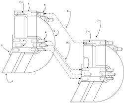
The figure shows the stacking method of two fully assembled and functional SYNCHRO-SYMs.
It’s possible to stack two fully assembled and functional SYNCHRO-SYMs (1) and (2). Each has its own bearing and frame assembly, axle assembly, and integrated electronic control. As a result, the power stack shows the accumulated power, which is independent from the wind-turbine rotor hub and bearing assembly. The stator (3) and rotor (4) are duplicate axial-flux disk assemblies. The axle assembly (5), which is attached to the rotor assembly (4), and the stator assembly (3) have bayonet plugs (6) that align and mate (8) with the bayonet sockets (7) to form a rigid but separate integrated stack of stators (3) and rotors (4) of multiple assemblies.
Looking at the figure, another method for mating “stators” would comprise a set of sliding frames (or rails) that span at least the full length of the stack of SYNCHRO-SYMs. The rails are a portion of the “stator” bayonet plugs (6) with a similar portion of sockets (7) configured as channel blocks for inserting the sliding frames. With each lightweight SYNCHRO-SYM component lifted to the nacelle and positioned onto the sliding frames by an internal nacelle crane, such as the rotor (4) and axle (5) assembly, the stator (3) and bearing assembly, or each complete SYNCHRO-SYM in the stack, the component would slide along the rails for alignment and attachment to another component inside the nacelle. As a result, all stators of the SYNCHRO-SYM stack are joined as one by the stator rails (or sliding frames) and stator bayonet methods (6,7). And separately, all rotors of the SYNCHRO-SYM stack are joined as one by the rotor bayonet method (6,7).
The same field installation and assembly process (using the internal nacelle crane as just discussed) is also utilized to replace or maintain any rotor, stator, or fully functional component within the entire stack. Or more importantly, it’s used to retrofit legacy wind-turbine systems, which have peaked their useful operational life.
Likely, the “legacy systems” have an obsolete mechanical gearbox, generator, and electronic drive, all of which can be hastily disassembled and removed, and then replaced with a small-diameter, low-speed, “direct-drive stack” of SYNCHRO-SYM components. Since the legacy electronic drive, gearbox, and generator upgrade is only 18% of total wind-turbine cost, the 80/20% tax credit rule is satisfied, while upgrading to a higher-performing, more efficient, more reliable, integrated, variable-speed wind-turbine system.
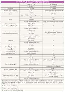
Using a computer-aided-design (CAD) tool specifically developed for the axial-flux SYNCHRO-SYM manufactured with MOTORPRINTER, called BEM-CAD, resulted in the table shown below. The table presents specification comparisons between the 12-MW Haliade-X wind turbine from GE and a resilient power stack of 12, small, lightweight, self-contained, 1-MW SYNCHRO-SYMs. Each SYNCHRO-SYM can be separated again into smaller rotor and stator components for easiest handling and transportation.
This table compares a GE 12-MW Haliade-X wind turbine with a power stack of 12, small, lightweight, self-contained, 1-MW SYNCHRO-SYMs.
BRTEC brings superconductor electric-machine systems closer to reality by exciting the conventional sinusoidally distributed active winding set with pure sinusoidal excitation waveforms, which reduces cryogenic refrigeration by avoiding harmonic heating of the superconductor electromagnet, and by brushlessly relocating the superconductor electromagnet to the stationary body (stator) for convenient logistical support. NOTE: When alternating-current (AC) superconductors become a reality, only the fully electromagnetic SYNCHRO-SYM will be the superconductor electric machine of choice.
Fred Klatt is Chief Technology Officer at Best Electric Machine.
About the Author

Fred Klatt
Chief Technology Officer
Frederick Klatt has over 50 years of successful high technology research, consulting, product development, and business development. He’s the inventor of the only practical symmetric synchronous doubly-fed electric machine circuit and control technology, called SYNCHRO-SYM, and the only practical 3D printer of electric motors, called MOTORPRINTER.
Fred holds a BSEE from Northeastern University, Boston, and a MSEECS from the University of California, Berkeley, and has over 40 years of research, design, development, and production experience. Fred has presented electric machine system technical concepts and knowledge at IEEE symposiums with published IEEE conference articles, e.g., SLED2012, ITEC2013, ESTS2013, IEMDC2013, & ITEC2014.


