E-Fuses, Ideal Diodes Overcome Shortfalls of Traditional Supply-Protection Devices
Among passive electronic components, the fuse and diode are well known, well understood, widely used, and essential to many circuits and systems. Still, each has inherent shortcomings that make them inadequate or limiting, especially in today’s low-voltage circuits.
By reimagining them via active components like op amps and MOSFETs, they can be enhanced with attributes that make them a good fit for many situations. These include overcurrent transients and protection against reverse-polarity connection of the battery in the automobile or LED lighting strings (which does happen and would cause serious damage to the electronics).
The Electronic Fuse: Eliminating Thermal Activation
The standard thermally activated fuse (also called a fusible link) has been in use as a current-limiting protection component for over 150 years, and its simplicity is one of its virtues. The functionality is straightforward: a current over the design limit heats the internal wire, which then melts and opens the current path, thus reducing the current flow to zero. It’s effective, relatively simple, and inexpensive, and fuses are available with ratings from a fraction of an amp to hundreds of amps.
However, the thermal fuse has several drawbacks, beginning with the time it takes to react. Depending on the overcurrent value compared to the threshold, it can take anywhere from tens of milliseconds to tens of seconds to react and open the circuit. In today’s lower-voltage designs, the overcurrent is often a modest value, so the fuse reaction time may be too slow to protect sensitive circuitry. Also, the standard fuse must be physically replaced after it opens, which is a disadvantage in many (but not all) applications.
The e-fuse provides an alternative approach to current limiting and cut-off with unique advantages, as it’s an all-electronic fuse that doesn’t depend on the thermal heating and subsequent open circuit of an in-line element. An e-fuse is built from several analog components: a precision current-sense resistor; an amplifier with accurate scaling resistors for capturing and “gaining-up” the voltage across the resistor; a comparator circuit to “switch” at the preset value; and a MOSFET to allow/break the path of current flow in the line being monitored (Fig. 1). In addition to circuit-protection applications, e-fuses are widely used in hot-swap controllers where the current inrush, which occurs when inserting a card into a live bus, must be monitored.
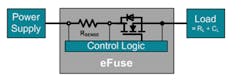
Typically, the resistor value is chosen so that the voltage drop across it will be between 50 to 100 mV at maximum current. The e-fuse is connected between the power rail (or supply source) and the load to be protected.
The circuit function is fairly straightforward. The current to be monitored passes through the resistor, and the resultant voltage across this resistor is sensed and scaled by the current-sense amplifier (CSA). Since the resistor value is known, it’s easy to utilize analog circuitry to set a threshold on the current passing through it using basic Ohm’s Law: I = V/R. If the threshold is exceeded, the comparator that controls the FET turns the FET off to interrupt the current. Response time is on the order of microseconds, far faster than a thermal fuse.
For the e-fuse to be truly useful, possible error sources must be understood. First, the resistor and scaling circuit must be accurate and have minimal temperature drift. The resistor value will deviate from nominal value due to changes in ambient temperature, as well as unavoidable self-heating of the resistor (which can cause significant errors). Therefore, the resistor power rating must be commensurate with the dissipation. Also, the on/off FET must be sized for the situation and may need its own gate driver, depending on its current and voltage rating. Second, the circuit which “trips” on the overcurrent must be properly designed to not have false positive or negatives. Usually, some hysteresis is added to prevent this chatter.
In nearly all designs, the CSA isn’t a simple op amp—rather, it’s a differential amplifier (diff amp). This is because in most configurations, the sense resistor isn’t connected on the grounded side of the load (assuming the load even is grounded). Instead, it’s connected on the high side and thus the CSA must measure the voltage without any ground connection. This also means the CSA must be rated for operation at the common-mode voltage (CMV) across the ungrounded resistor. CSA ICs are available that can easily measure microvolts within the 100-mV range, yet tolerate common-mode voltages of 50-100 V (as well as negative CMVs) without degrading their accuracy or basic function (or even being damaged).
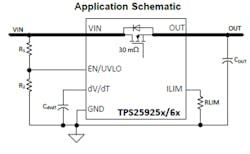
While it’s possible to build an e-fuse from individual components, most users instead opt for a complete IC-based e-fuse that incorporates the needed circuitry including the FET. Some even have an internal sense resistor. IC-based e-fuses can also include additional functions and features, such as user-programmable undervoltage lockout, overvoltage clamp, and auto retry, as well as a startup time that can be set by means of external components (Fig. 2). That last feature is useful to keep in-rush current under control during startup and hot-swap operations, which is why such e-fuses are of found in that application.
Fortunately, despite their internal complexity and additional features, these e-fuses are fairly easy to use. Some e-fuses have received recognition from UL (formerly known as Underwriters Laboratories) and comparable world-side regulatory safety agencies, which further broadens their applicability.
The Ideal Diode: Slashing Forward-Voltage Drop
A reverse-connected battery or power rail can cause havoc and damage to sensitive electronic circuits. The problem is especially acute in cars, where the battery must often be disconnected and reconnected manually, without keyed connectors. Even a momentary reversal can damage or weaken sensitive circuit components.
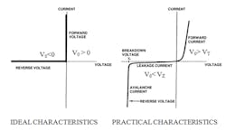
The obvious solution is to use a standard PN semiconductor diode in series with the supply rail or rails to the subcircuits. This ubiquitous diode is an essential component with a simple basic function: It blocks the flow of current in one direction (reverse bias) but allows it in the opposite direction (forward bias).
But it’s a solution that unleashes a new problem. When conducting in the forward-biased direction, there’s an unavoidable voltage drop of 0.6 to 0.8 V across the standard silicon diode. While this drop may be insignificant in some designs, it ranges from being somewhat significant in others, to being unacceptable in systems where the operating voltage itself is just a few volts (e.g., the 12-V nominal rail of most cars or the lower-voltage subcircuits). Not only is there a loss of voltage, but there’s power dissipation and detrimental self-heating due to the dissipation of this diode.
One solution is to go with more expensive Schottky diodes. They have a much lower forward drop of about 0.3 V, and are often used in place of conventional diodes for this reason. However, they have other less desirable attributes, such as higher reverse-leakage current, which makes them more challenging to use. Even so, their ~300-mV drop is still a significant fraction of the available voltage in a 12-V system (and even worse in a lower-voltage subcircuit).
A better solution is to use an “ideal diode” built with active devices for reverse-polarity protection. Note that the term “ideal” is somewhat of a misnomer, since a truly ideal diode would have a forward drop of zero volts (Fig. 3). However, the active “ideal” diode comes fairly close with its forward drop about 30 to 40 mV, which is an order-of-magnitude less than even the Schottky diode. Regardless of the accuracy of the designation, the industry refers to these as ideal diodes.
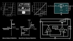
To understand the ideal-diode operation, we can use the Analog Devices LTC4358 as an example (Fig. 4). This 12-V/5-A IC contains an internal 20-mΩ MOSFET as the pass element and doesn’t require any external components. The IN pin connects to the source of the MOSFET and functions as the anode of a diode, while the drain connection functions as the cathode. When power is first applied, the load current initially flows through the MOSFET’s body diode, and the MOSFET’s gate is enhanced and turns on to maintain a 25-mV forward-voltage drop.
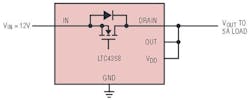
If the load current results in a forward-voltage drop of more than 25 mV, the MOSFET is driven to its fully on state, and the forward drop equals RDS(ON) × ILOAD. If the load current is reversed and the FET thus reverse-biased (as may occur during a short circuit at the input), the LTC4358 turns the internal MOSFET off in less than 0.5 μs.
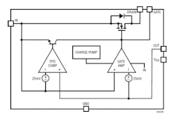
The on-resistance of the MOSFET is the key parameter that determines how close to “ideal” this ideal diode can become. As with nearly all semiconductors parameters, RDS(ON) is a function of temperature, a factor that must be used in any circuit modeling, simulation, and analysis. Note that the internal circuit of the ideal diode is somewhat complicated (Fig. 5), but this complexity is invisible to the user. The ideal diode is connected like a simple two-terminal device plus ground.
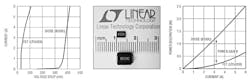
The ideal diode not only reduces forward-voltage drop, but it also lowers the associated power dissipation as a consequence. For example, compare the LTC4358 to the widely used B530C Schottky diode in a surface-mount-component (SMC) package. The LTC4358’s 4- × 3-mm DE14 package has one-fourth the footprint of the SMC package, while the voltage drop and power dissipation are also far less (Fig. 6). Furthermore, the much lower power dissipation at 5 A current in the Schottky diode (2 W versus 0.5 W for the LTC4358) greatly increases system efficiency, simplifies board layout, and trims BOM and cost as no heat sink is required.
Both e-fuses and ideal diodes are active, more sophisticated versions of the venerable thermal fuse and PN diode, respectively. While they may seem more complex, both are easy to use and overcome many of the shortcomings of these older components at little or no cost. They usually will also reduce overall system-level complexity and cost when looking at the “bigger picture” of the design.
References
Analog Devices, LTC1153 Auto-Reset Electronic Circuit Breaker Datasheet
STMicroelectronics, STEF01 8 V to 48 V Universal Electronic Fuse Datasheet
Texas Instruments, TPS25925x, TPS25926x Simple 5-V/12-V eFuse Protection Switches
Texas Instruments, SLVA862A, “Basics of eFuses”
Maxim Integrated, Design Solutions No. 50, “Cut Your Losses—With an Ideal Diode”
Maxim Integrated, Design Solutions No. 51, “Design a Cooler, Safer Smart-Home Hub—Using an Ideal Diode”
Analog Devices. LTC4358 datasheet
Analog Devices, “Ideal Diode Betters a Schottky by a Factor of Four in Power and Space Consumption”
Texas Instruments, “Ideal diode & ORing controllers
Electronic Design, “Reverse-Polarity Protection in Automotive Design”