What's the Difference Between AC-DC and DC-DC Power Supplies?
Making a dc voltage from an ac source means you will have to rectify the ac voltage to get a dc bus. One difference compared to a dc-dc converter is that you can use a linear power supply with an ac voltage. That means you can take advantage of using a transformer to reduce or increase the ac voltage, and then rectify the result. The closest thing to a linear dc-dc power supply would be a dc motor driving a dc generator, which isn’t a very efficient proposition.
Linear ac-dc power still has a place in lab supplies and high-end audio, but most modern power conversion uses switching voltage regulators, not linear ones. In this application, you will be rectifying the incoming ac voltage to create a dc bus. Once you have this dc bus, you can use any of the dc-dc power-conversion architectures to make the final output voltage or voltages you need.
The Problem with Rectification
While conceptually simple, rectifying the incoming ac adds a host of problems to your power supply. Most rectification is done with diodes. Those diodes will create switching spikes as they work, which can send conducted noise back into your wall outlet. They also will have a forward voltage drop that consumes power.
You can use a MOSFET bridge to rectify the incoming ac, but it’s a significant control challenge. I have a friend who did this for the Nest thermostat, which is powered off the 24-V ac used for conventional thermostats. This is a real power challenge, since turning on the furnace or air conditioning is based on shorting that 24 V ac at the thermostat—that’s how a conventional thermostat works. The Nest draws a very small current to charge its batteries. It can then short the 24-V ac input to turn on the furnace, using the same FET bridge, while it runs on batteries. The Nest thermostat needs every small bit of energy it can get; hence the need to eliminate a simple diode bridge.
Rectifying ac has other problems, such as the surge current that it will draw (Fig. 1). This is different than inrush current, which dc-dc supplies also have, when you first apply power to them. Surge currents come about because the rectifying diodes can only conduct when the input ac voltage is greater than the dc bus voltage you’re creating. That means there’s a short surge of current only at the ac voltage peaks. This causes the power factor of an ac supply to be poor. Power factor is a measure of the coherence of the voltage and current supplied by the ac line.
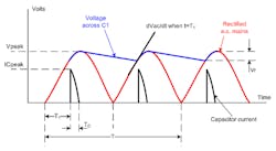
1. When a diode bridge rectifies an ac input, current only flows when the incoming ac voltage is greater than the dc bus voltage it’s creating. This causes current surges during a small period of the waveform, which reduces the power factor. (Courtesy Jose Soares Augusto, quora.com)
For inductive loads, such as motors, the ac current will lag the ac voltage. For a capacitive load, the current leads the voltage. In both cases voltage and current are out of phase, so the power factor drops from the ideal of “1.” With rectification, the power factor drops for a different reason. While the surge of current might be in phase with the voltage, it only happens for a short period of the ac waveform.
Correct Your Power Factor
While poor power factor will not increase the cost of the electricity to you, it does mean the power company needs larger wires to carry the intermittent current loads. Many countries have developed standards that require your off-line ac supply have power factor correction (PFC). PFC makes sure the input current to the power supply is a sinusoid that’s in phase with the input voltage.
PFC adds another switching regulator to your ac-dc power supply. The PFC front end is usually a boost converter (Fig. 2). Since it’s boosting the input ac to a higher voltage, perhaps 350 V dc, the converter can draw current from the ac line at almost all times of the waveform. The control chip will pulse width modulate (PWM) the boost converter transistors to make the current drawn from the ac line directly proportional to the voltage. It can’t draw current at the zero crossings, so the power factor can’t be perfect. However, it’s possible to get above 0.9, which solves the major problem.
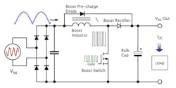
2. A power-factor-correction (PFC) front end is usually a boost converter that can draw current from the ac input for all of the input cycle.
In addition to the need for rectification in an ac-dc power supply, differences exist in how you rectify the ac line. Worldwide ac mains voltages can range from 100 V in Japan to 240 V in Europe. In old linear power supplies, you could have the user throw a switch to change a winding tap on the input transformer to accommodate these different voltages. With a switching supply, the switch could change the wiring; therefore, you use a full diode bridge with the high voltages, and a half bridge with the lower voltages (Fig. 3). This allows the dc bus you create to be closer to the same value, even though the input ac has halved in voltage.
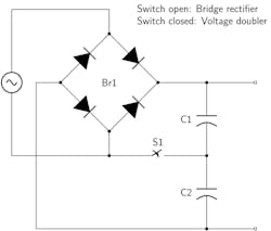
3. Adding a switch to a bridge rectifier will change it into a voltage doubler that uses two of the diodes. This allows you to double 120-V inputs, and bridge rectify 240-V inputs, making the dc output voltage the same. You can detect the voltage with circuity and use an automatic electronic switch. (Courtesy of Wikimedia)
With the rising availability of silicon-carbide (SiC) MOSFETs, many PFC front ends use totem-pole rectification (Figs. 4 and 5). SiC has a negligible reverse-recovery time, so there’s no shoot-through in the rectification. The two SiC FETs cost more than two diodes, but the efficiency gain may be worth it to you. Once the SiC and control chip rectifies the ac while maintaining power factor, you then have a high-voltage dc bus with which you can use any of the dc-dc converter architectures to make your final output voltage. You can also use the dc-dc stage to create an isolation boundary if desired.
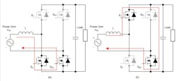
4. A totem-pole PFC circuit works as a boost converter. With positive input as indicated by the plus and minus signs on the source, current builds up in the inductor when S2 is closed (a), and then flows into the load via S1 (b). SD2 could be a diode, but a SiC transistor improves efficiency. (Courtesy of Texas Instruments)
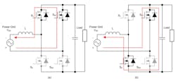
5. When the ac input goes negative on a totem-pole PFC circuit, transistors steer current in the inductor in reverse (a). When S1 opens and S2 closes, it sends current into the load (b). SD1 could be a diode, but a SiC transistor improves efficiency. (Courtesy of Texas Instruments)
A Plethora of Standards
A major difference between ac-dc and dc-dc supplies is that ac-dc supplies must comply with far more regulatory standards. Both supplies have FCC and CE standards for electromagnetic noise, but the higher voltage of ac-dc supplies makes them subject to fire and safety standards. Since most ac-dc supplies have isolation from the wall voltage, that also requires UL, CSA, and CE listings.
If you are making a medical device, you may need even more stringent designs. Whereas isolation in a conventional supply can happen just with the wire insulation in the transformer, medical transformers put the windings on completely separate bobbins (Fig. 6). Thus, there’s no chance that a short can occur between primary and secondary, which might kill a patient.

6. These Signal power transformers have a split bobbin to improve the safety in ac-dc converters. (Courtesy of Digi-Key)
The standards that apply to your ac-dc supply will vary by application. Different standards exist for information, medical, and telecommunication products. There are also different regulations for Class I, where the plug has a ground pin, and Class II, often called “double insulated,” where the power supply isn’t connected to earth ground. In addition, there’s a limited power source (LPS) class with relaxed safely specs due to the limited nature of its power availability. The body of regulations are so complex, many designers turn to an outside listing company, like UL or TUV or the dozens of testing laboratories that are familiar with all of the worldwide standards for your particular product application
Noise and Immunity Considerations
The FCC and European CE have standards for radio-wave emissions from all supplies, both ac-dc and dc-dc. But it’s more complex and difficult to pass requirements for ac-dc supplies. Not only do you have regulations on the amount of radiated electromagnetic interference (EMI), you have to test your ac-dc supply for conducted noise; that is, the noise that it injects back into your wall power. Since ac-dc supplies are often slewing large currents over large voltages, they will radiate much more than a dc-dc supply, so passing EMI regulations will be more difficult.
In addition to the conducted EMI requirements, your ac-dc supply will have conducted immunity requirements. This is where you have to inject EMI into the line cord and prove that your supply isn’t affected. Like a dc-dc supply, it also must have immunity to radiated EMI.
All of this is on top of the EMI, fire, safety, and green energy requirements of an ac-dc supply. Power Integrations has a good site showing some of the requirements on ac-dc supplies, such as the “vampire power” that an ac-dc supply consumes even when it’s off.
While some engineers avoid the challenge of ac-dc supply design, including the danger of developing high-voltage circuits, there is a growing breed of analog engineers that welcomes the challenge, and the rewards, of making safe, efficient, and green products that push the state of the art.