Simple, Low-Cost Dynamometer Setup for Motor Testing (Part 1)
Download this article in PDF format.
A dynamometer is a testing device that helps engineers collect data for various mechanical loading conditions that a motor or engine might encounter in a particular application. Other than testing the motor itself, a dynamometer helps engineers test how their motor-control algorithms and motor-driving power electronics respond to these conditions. In my role as an applications engineer at Texas Instruments (TI), I needed a better way to test various loading conditions on small motors.
From August 2018 to May 2019, I had the opportunity to work with an excellent group of engineering students in the UTDesign program at the University of Texas at Dallas to do just that. They called themselves the Motor Torque Test Bench team (MTTB). In this first article, I review the technical questions we needed to answer even before making our component selections.
Requirements
This dynamometer had to operate at low speeds, provide accurate torque, and produce torque profiles like ramps and square waves. The torque profiles would be helpful for verifying the performance of motors and driver ICs when driving a varying mechanical torque load. It also had to look nice in case it’s ever taken to a customer or a tradeshow for a product demonstration.
Creating Torque
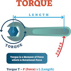
The first question to answer in the design project is, “How can I produce torque?” From basic physics classes, we know that torque is the cross product of the length of the lever arm and the force applied to it (Fig. 1).
At first pass, using some kind of frictional braking or a system of pulleys and weights seems like an easy solution. However, these methods don’t easily allow the torque to vary with time or position without some more-complex mechanical assembly. We also considered hysteresis brakes, but had concerns about cogging torque, repeatability, and overall performance at low speeds. Given the limited time and resources of a senior design project, the MTTB team decided against using a hysteresis brake for the dynamometer load.
Selecting a Motor for the Active Load
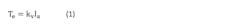
Eventually, the team decided to use a motor for the active load, but we needed to decide what kind of motor. Brushed dc motors are the easiest to control. Torque is directly proportional to the current in the motor, as shown in Equation 1.2 The torque produced by the motor is Te, the torque constant determined by the construction of the motor is kv, and the motor current (or armature current) is Ia.
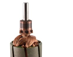
However, when the MTTB team tested a few brushed dc motors on prototype setups, we saw large ripples in the current waveforms and the motors were noisy. The noise is likely due to torque ripple from the brushed dc motor. Current ripple is a common cause of torque ripple (cogging torque is another cause of torque ripple).4 In the brushed dc motor, as the brushes switch positions on the commutator, this causes ripples in the current and torque. Figure 2 shows an example of a brushed-dc-motor commutator.
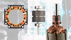
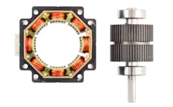
Torque ripple is something we needed to minimize for smooth torque profiles. This meant that we should also avoid using a stepper or a brushless dc (BLDC) motor (Figs, 3 and 4, respectively). A stepper motor is a “doubly salient” motor and would have high cogging torque since it has teeth on the rotor and the stator.1
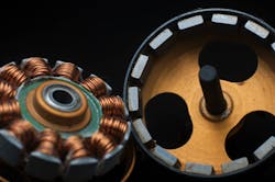
A BLDC motor will have torque ripple from cogging torque and the trapezoidal shape of the back EMF due to the winding geometry.5 The shape of the back EMF indicates the shape of the magnetic field created by the stator windings in the air gap. The magnetic field will also have a trapezoidal shape and will not be smooth since individual coils are wound around individual stator teeth.
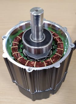
However, a surface-mount permanent-magnet synchronous machine (PMSM) is similar to a BLDC motor with minimal cogging torque and a sinusoidal shape for the back EMF. Figure 5 shows the inside of a PMSM motor. The surface-mounted magnets, sinusoidal windings, and smooth rotor and stator construction (no teeth) are all features that minimize torque ripple and cogging torque in this motor.
The control algorithm required to drive the motor is just as important as selecting the motor itself. For the PMSM, field-oriented control (FOC) is the best way to smoothly control torque (as opposed to other ways, such as trapezoidal control) with a fast response time (as opposed to voltage control methods). FOC uses the Clarke and Park mathematical transformations to directly control the motor torque by regulating the current in the windings based on rotor position. To oversimplify: FOC controls BLDC motors similarly to how one would control torque in brushed dc motors. Equations 2 and 3 illustrate this point.2


Equation 2 shows the PMSM torque using variables indicating the actual currents and voltages of the phase windings.2 Number of poles is P. Flux linkage is λˊm. The phase currents are ias, ibs, and ics (these must be sinusoidal currents, each phase shifted by 120°). The rotor displacement is θr. Equation 3 shows the torque equation after the variables are transformed to the rotor reference frame.2 The sinusoidal currents in Equation 2 are replaced by a constant dc current, Irqs. Equation 3 looks similar to Equation 1 used for the brushed dc motor. This video explains FOC and the Clarke and Park transforms in greater detail.
To implement FOC, shaft position needs to be measured or estimated. Many sensorless BLDC control algorithms require measuring the back EMF of the motor to estimate rotor position mathematically. Since the dynamometer will operate at low speeds, the back EMF may not be large enough to measure. The MTTB team decided to use an encoder to measure rotor position with high resolution.
Conclusion
From this initial investigation, the MTTB team decided to implement the active load of the dynamometer using a PMSM controlled by FOC. In the second article, I discuss their final implementation, including component selection, hardware, software, and where to find their open-source files.
Acknowledgements
- University of Texas at Dallas UTDesign staff and students (listed as contributors on the Hackster page)
- Chris Clearman for recommending the LaunchPad, BoosterPack, and InstaSPIN firmware to get us started on development.
- David Magee, Rajan Narasimha, and Stephen Fedigan for our discussions on dynamometer designs earlier in the project.
James Lockridge is a systems engineer within TI’s motor-drives business.
References
1. Acarnley, Paul P. Stepping motors: a guide to theory and practice. 4th ed., Institution of Engineering and Technology, 2007.
2. Krause, P. Wasynczuk, O. Pekarek, S. Electromechanical Motion Devices, IEEE, 2012.
3. Hysteresis Brakes and Clutches 2nd edition, www.magtrol.com. November 2011.
4. “Understanding the Distinctions Among Torque Ripple, Cogging Torque, and Detent,” Tech Papers, Motion Control Resources. www.motioncontrolonline.org. August 15, 2013.
5. Akin, B. Bhardwaj, Warriner, J. “Trapezoidal Control of BLDC Motors Using Hall Effect Sensors,” www.ti.com. April 2011.