How to Design an Optimal Electronic Load for High-Current, Low-Voltage Power Supplies (Part 2)
Download this article in PDF format.
Part 1 of this article showed how an active current-sink circuit can address all the requirements for testing high‑current, low-voltage power supplies. However, successful implementation of this circuit does present some design challenges. Careful selection of the circuit components is critical to the performance and durability of the final electronic load circuit.
MOSFET Selection
The power transistor must be chosen to provide fast response while also withstanding high power dissipation. Several electrical and thermal characteristics must be considered:
Gate Charge
To modulate the current flowing through the MOSFET with good stability and high bandwidth, the operational amplifier must be able to rapidly change the gate-to-source voltage. A MOSFET with high gate-to-source and gate-to-drain capacitances (CGS and CGD, respectively) will require higher drive current to reach a desired slew-rate. Therefore, it’s important to select a MOSFET with low “figure of merit”1 and correspondingly low parasitic capacitances. For many MOSFETs, the total gate charge QG is a good metric, and comparisons between MOSFETs of similar on-resistance RDS(ON) can be made quickly, using just this parameter.
Drain-Source Voltage
The drain-to-source voltage (VDS) must be high enough to withstand the voltage of the supply under test, including any transient surges or overshoot. Most discrete power MOSFETs are rated for 12 V, 25 V, 30 V, or even higher, so selecting a MOSFET with VDS suitable for testing low- to mid-voltage supplies isn’t difficult. In general, the MOSFET should be chosen with VDS rating that is at least 125% of the voltage to be tested. A higher VDS rating in the same-size transistor will negatively impact other performance characteristics, so choose a device with the lowest acceptable VDS rating.
Drain Current Rating
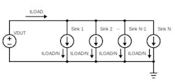
The drain-to-source current rating ID(MAX) of the MOSFET must be adequate to pass the desired load current. When very high currents must be generated, using an array of parallel current-sink circuits eases the power dissipation and IDS requirements for the individual MOSFETs. In other words, if an array of N equal active-current sinks is used (Fig. 1), the current through each current-sink MOSFET is the total load current divided by N.
Note that a single operational amplifier can control several MOSFETs in parallel (Fig. 2), provided that each MOSFET is connected to an independent sense resistor at its source terminal. This scheme ensures that the total current is shared evenly between MOSFETs, because of the source-follower negative feedback characteristic described earlier.
When driving two or more MOSFETs in this manner, it’s usually necessary to add small resistances in series with the MOSFET gates to prevent oscillation. The difference-amplifier configuration is further extended to include summing by duplicating the feedback and input-divider resistances into each leg of the circuit. This isolates the two sense resistances to preserve the independence of their negative-feedback effect on each MOSFET.
Transistor Package
Perhaps the most important characteristic of a MOSFET used in an electronic load is its ability to dissipate waste heat. The total power in the load (PL) is obviously the product of load current and the voltage under test:
PL = ILOAD × VDUT
If quantity N current-sink circuits are operated in parallel, each current-sink “branch” carries ILOAD/N, and the total load power is distributed more or less evenly between the branches.
Some portion of this power is dissipated in the sense resistors (PR), and this portion varies as the square of the load current:
PR = (ILOAD / N)2 × RSENSE
The remainder of the power is dissipated in the MOSFET (PM):
PL = (PM + PR) × N
PM = PL / N – PR
PM = (ILOAD × VDUT) / N – (ILOAD / N)2 × RSENSE
The ability of a MOSFET to dissipate heat is summarized by two key parameters: the junction-to-case thermal resistance ΘJC and the steady-state power dissipation PD(MAX). Of these two, the ΘJC value is most useful, as it indicates the lowest possible temperature rise of the MOSFET junction as a function of power, excluding all effects of the external environment.
While the MOSFET datasheet will also probably provide a case-to-ambient thermal resistance value ΘCA, this value is determined by a standard PCB size and construction.2 The high-power electronic load will be designed expressly to maximize heat dissipation, with considerably lower thermal resistance than the typical free-air junction-to-ambient thermal resistance ΘJA values that appear in MOSFET datasheets. In other words, because the high-power electronic load will require a heatsink that’s quite different than the standard ΘJA test board, the ΘJC value is most useful.
In addition to the thermal-resistance characteristics of the device package, the maximum junction temperature of the MOSFET silicon TJ(MAX) must also be considered. Most power MOSFETs are rated for TJ(MAX) = 150°C to TJ(MAX) = 175°C. The electronic load must be designed such that the product of the MOSFET power PM and package thermal resistance, combined with the maximum device mounting-surface temperature, or case temperature TMB = TC, doesn’t exceed TJ(MAX):
PM < (TJ(MAX) – TC) / (ΘJC)
Depending on the choice of unknowns, this relationship yields either the maximum allowable steady-state power for the MOSFET, or the maximum allowable heatsink temperature at the desired maximum steady-state power.
Safe Operating Area
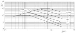
The power MOSFET datasheet will include a safe-operating-area plot, or SOA. This plot shows the continuous (dc) pulsed-power capability of the MOSFET. The SOA plot for the Nexperia PSM2R0-30YLE is shown in Figure 3.
Note that the SOA plot is generated for a fixed mounting-base temperature (TMB). In Figure 3, TMB = 25°C. The 100-A package limit appears as the flat portion of the dc curve at IDS = 100 A, and for VDS, below about 1.3 V. The total power limit PTOT = 272 W appears at the point where VDS = 1 V and IDS = 272 A. Additional curves show progressively higher peak power capability for progressively shorter pulse durations. It’s worth noting that the curves on the SOA plot are generally lines of constant power; in other words, a constant product of IDS × VDS.
The ability of the MOSFET to handle much higher power for brief pulses is very useful for an electronic load that’s intended to test transient response. That’s because the transients needn’t last any longer than the supply recovery time, typically measured in tens or hundreds of microseconds. Safe pulse power can be increased by reducing the pulse duration, and vice versa.
It’s important to design the electronic load such that the MOSFET doesn’t operate above its SOA curve for any intended pulse width, or MOSFET failure is likely. Desired operating points should be located on the SOA plot to ensure that the design will operate safely.
Some power MOSFETs are optimized for operation in the linear region and specifically designed to have more area under the SOA curve, compared to MOSFETs optimized for rapid on-off switching applications. For example, Nexperia’s NextPower Live product line is optimized for use in linear applications, such as hot-swap and soft-start. This added robustness in the linear region is also well-suited for use in an active current-sink circuit. The PSMN2R0-30YLE (see table) is a member of this product line and works very well in active electronic loads with high power dissipation.
Transient Thermal Impedance
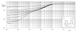
The MOSFET datasheet will also include a transient-thermal-impedance plot, such as the plot for the PSMN2R0-30YLE shown in Figure 4. The time-limited, transient thermal impedance of the MOSFET is lower than the steady-state thermal impedance because of the heat capacity of the device die, lead frame, and package materials.
Unlike the SOA plot, the transient-thermal-impedance plot isn’t a function of a specific TMB value. This makes it very useful for determining the MOSFET junction temperature rise above TMB for any given power-pulse width and duty cycle. As the duty cycle approaches 100% and the pulse width approaches dc, the transient thermal impedance plot converges with the steady-state value of the junction-to-case thermal impedance ΘJC. Some MOSFET datasheets will provide a normalized transient-thermal-impedance plot, so that the y-axis represents a fraction, from zero to 1, of the steady-state ΘJC value. It’s important not to confuse this unit-less, normalized fraction with an actual impedance value in °C/W.
For example, using Figure 4 , if the MOSFET experiences a 200-W pulse that is only 100 µs in duration at 10% duty cycle (in other words, a 100-µs pulse that repeats at 1-kHz frequency), the effective transient thermal impedance is only about 0.075W/°C, compared to the steady-state value of ΘJC = 0.55°C/W. The product of this transient thermal impedance and the 200-W pulse magnitude yields a predicted rise in TJ of about 200 W × 0.075°C/W = 15°C.
Sense Resistor Selection
Power and Current Capability
Much like the power MOSFET, the sense resistor in an active current-sink circuit is also expected to dissipate a significant fraction of the total load power. It’s important to select a sense resistor that can not only handle the full load current of each parallel branch of the current sink, but also transfer waste heat rapidly to the PCB and heatsink.
A good sense resistor will have all the following mechanical characteristics:
- Large electrical connection area to the PCB copper traces or pours.
- A package that can be coupled to top-side cooling (the heatsink) with low thermal resistance.
- Resistive element and package materials that can withstand high operating temperatures.
The first characteristic favors surface-mount components, because through-hole resistors only connect electrically with the PCB at two through-hole pads (one for each wire lead). The wire leads also present a significant resistive and inductive bottleneck to the load current. Furthermore, most leaded packages are more challenging to thermally couple to the PCB and heatsink for effective cooling.
Surface-mount resistors have two key advantages: they're soldered to wide pads on the PCB and usually have a thin, flat package that makes it easy to establish a low-resistance thermal connection to the heatsink. Current can be conveyed from inner-layer copper in the PCB to the top-layer pads through use of stitching vias, often within the resistor pads themselves.
The element of a surface-mount resistor will usually either be a conductive film or foil on a ceramic substrate or a solid metal element. Of these two, the metal element will likely be more robust when operating at high power.
Package materials are important to thermal performance as well. A sense resistor that’s encapsulated in plastic has the advantage of being electrically isolated from the heatsink. However, the encapsulation usually presents a higher thermal resistance than the element itself, so unencapsulated devices can achiever lower overall thermal resistance.
Low Parasitic Inductance
Parasitic inductance in the sense element (LSENSE) directly limits the maximum current slew-rate that can be achieved in the electronic load, because the current can’t rise faster than the inductance allows:
dI/dt ≤ V / LSENSE
Furthermore, at high current slew-rates, parasitic inductance causes the voltage across the sense element to deviate from the true load current. Instead, the transient voltage across the resistor is the sum of the resistive voltage and the inductive voltage:
ISENSE = (VSENSE / RSENSE) × (1 – e-t/τ)
VSENSE = (ISENSE × RSENSE) / (1 – e-t/τ)
τ = LSENSE / RSENSE
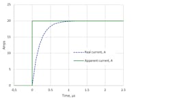
The current-sink amplifier circuit can’t distinguish the inductive portion of the signal from the resistive portion, so the actual load current rises more slowly than the sense-resistor voltage signal (Fig. 5).
In Figure 5, the “apparent current” is the voltage across the sense resistor, which is controlled to a constant value by the operational amplifier in the current-sink circuit, responding to a step in the input control voltage (the “load waveform” of earlier examples). The “real current” lags the sense-resistor voltage, with time constant τ ≈ 200 ns. The actual current agrees with the sense signal only after about 5 × τ = 1 µs has elapsed, rendering the circuit ineffective for generating faster load transients.
This lag presents a problem for both the current-sink and the current-measurement circuits—both must be compensated for this time constant. The inductive signal can be cancelled by applying a single-pole low-pass filter to the sense signal. This can be as simple as an R-C filter across the sense resistor, or it could be implemented in the operational-amplifier feedback loop. The filter should be chosen such that the time constant matches the sense resistor:
τ = RFILTER × CFILTER = LSENSE / RSENSE
If the filter is added across the sense resistor, care must be taken to ensure that the dc gain of the current-sink difference amplifier isn’t altered.
To alleviate the problem before it occurs, choose a low-inductance sense resistor. A resistive element that’s short, wide, and thin will exhibit lower inductance than one of the same value that’s long and thin, or one that relies on a serpentine path to increase resistance.
Importance of Sense-Resistor Precision
While not critical for load-transient testing, the absolute accuracy of the electronic load is extremely important if the measured current will be used to calculate the efficiency of the power supply under test. The electronic load can never be more accurate than the sense resistor itself, so it’s important to select a sense resistor with high precision.
Because the sense resistor will also be dissipating power, the temperature coefficient of resistivity (TCR) plays a significant role in the accuracy of the load over a wide range of power. As the resistor heats up, its resistance also increases, typically in direct proportion to the temperature.
RHOT = RNOMINAL × (1 + (THOT − 25°C) × TCR)
Thankfully, many suitable sense resistors have TCR values at or below 50 ppm/°C. This is equivalent to a change in resistance of just 0.5% with 100°C rise in temperature. If further precision is required, a temperature-measurement circuit can be added to the electronic load. Current measurements can then be corrected after collection, based on the TCR value from the sense-resistor datasheet and the element temperature at the time the measurement was captured.
A sense resistor with separate, dedicated power and sense connections helps improve precision as well. By splitting the connections into a high-current path and a low- or no-current path for sensing, the current being measured doesn’t add more voltage drop in the sense connections. This is commonly referred to as a Kelvin connection, or more generally as four-terminal sensing.
Many sense resistors are constructed in this manner, particularly when the resistor is designed for high current and low resistance. Even if the sense resistor doesn’t have physically separate sense pins, the datasheet will often describe the proper connection points and trace routing for best precision.
Maximum Current Consideration
The maximum current capability of the electronic load is a simple function of the voltage of the supply under test and the combined resistance of all the MOSFETs and sense resistors, with the MOSFETs fully enhanced. To prevent amplifier saturation at the highest load current, the design should have a total series resistance that’s substantially lower than the voltage under test divided by the maximum required current:
RLOAD,MIN = (RDS(ON) + RSENSE) / N
RLOAD,MIN < VDUT,MIN / ILOAD,MAX
This allows the operational amplifier to keep the MOSFET in the linear region at the maximum commanded current. If the commanded current rises above the ILOAD,MAX value, the current-sink circuit will enter saturation, driving the MOSFETs fully on, but can no longer maintain closed-loop control of the load current.
Power Design
Because the active current-sink circuit controls the load current by keeping the MOSFET in the saturation region, the MOSFET dissipates most of the power in the electronic load. The sense resistor also dissipates power, proportional to the square of the load current. Since the resistor and the MOSFET both dissipate significant power in a load application, they must be chosen carefully. Good thermal design is very important to avoid damage caused by excessive heat.
Splitting Full Power Evenly
If both the MOSFETs and the sense resistors have similar power capability, the design of the electronic load can be roughly optimized by splitting the power dissipation evenly between the MOSFET and the sense element at maximum current. This is accomplished by setting the sense resistor value about equal to the RDS(ON) of the MOSFET. This method also minimizes the peak power in both the sense resistors and the MOSFETs.
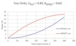
The plot in Figure 6 shows how the power dissipation in the MOSFET and sense resistors varies with load. If either the MOSFETs or sense resistors are a limiting factor for overall power dissipation, the balance of the RLOAD,MIN resistance can be shifted to reduce the power in either the MOSFET or sense resistor, at the expense of higher peak power in the opposite component.
Using this scheme, at current levels below maximum, the MOSFET will always dissipate more power than the sense resistor, because most of the voltage drop occurs across the MOSFET. Of course, the balance of power dissipation also varies strongly with the voltage of the supply under test. The combined resistances must be low enough to accommodate the highest desired current at the lowest VDUT,MIN. Worst-case power dissipation occurs at the highest voltage under test VDUT,MAX.
Operational Amplifier Selection
The operational amplifier must have adequate output capability to drive the gate of the MOSFET, which presents a capacitive load to the op amp. Bandwidth and voltage slew-rate are also important considerations when choosing the operational amplifier, especially when high load-current slew rate is required.
Single-Supply Operation
Because the electronic load should exhibit linear response from zero load to full load while operating from a single supply voltage, the op amp must have rail-to-rail input capability. At the least, it should be able to accept inputs that swing to the negative rail (ground in this case).
Rail-to-rail output isn’t necessary because the MOSFET stops conducting when the op-amp output is less than the gate threshold voltage VGS,TH. However, the op amp and its supply must be chosen such that the MOSFET gate can be driven high enough to achieve the maximum desired load current. This means that the op-amp output voltage must be able to exceed ILOAD,MAX × RSENSE + VGS,TH. This consideration rapidly narrows the range of suitable operational amplifiers, because many high-performance, single-supply devices are limited to +5-V power. Fewer op amps are available that can accept a +12 V or higher supply voltage.
Precise Op Amp for Better Accuracy
A precise operational amplifier will yield better accuracy of load current versus the input control signal. This makes the load easier to use and more consistent. Low input offset voltages can reduce or eliminate offsets in the load current, particularly when the control signal is at zero volts. Low input bias currents enable the use of higher input and feedback resistances in the differential amplifier circuit, which in turn improves the input impedance.
Current Monitoring
In addition to generating a fast, precise load-current transient, a useful electronic load will also include a means to monitor the load current. Typically, this is an output signal that can be connected to an oscilloscope input to allow for real-time graphical indication of the load current waveform.
If a separate amplifier is used to report the load current, a precision op amp can reduce or eliminate the need for calibration. This is especially helpful for very-high-current loads, where it may not be possible to find a precision shunt that can handle the full load current, making it difficult or impossible to calibrate against an external reference.
Voltage or Current Output Signal
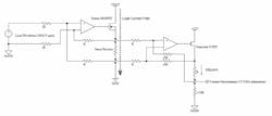
The most straightforward circuit for monitoring the current is a summing amplifier, generating a voltage output that is proportional to the load current.
One possible improvement is to convert the output of the summing amplifier into a current source (Fig. 7). This provides a current output that’s proportional to the load current.
Such an approach has some advantages over a voltage signal. Individual current-source outputs can easily be summed by feeding them into a single resistor to ground, thus allowing several load devices to report a total load current, without the need for an additional summing amplifier. Current-source outputs are also less susceptible to noise introduced by ground-potential shifts between the load device and the measurement equipment, especially if the summing resistor is located at the measurement equipment.
Precision Operational Amplifiers for Current Monitoring
The current-measurement or monitoring circuit can be optimized for precision or for speed and bandwidth. The former is important if the electronic load will be used for efficiency measurements, where the steady-state load current must be known precisely. The latter is important for analysis of transient response, where the shape of the load-current waveform is critical to accurate representation of the load-current slew rate.
Fortunately, in many cases, a good compromise can be achieved between speed and precision. Amplifiers with higher precision typically maintain lower bandwidth, while faster amplifiers generally have higher input offset voltages and bias currents.
Regardless of whether the reporting circuit is optimized for speed or precision, the design is simplified if the amplifier can operate from a single supply. The ability of the output to swing rail-to-rail is also critical for voltage-output designs, in order to allow for indication of low-load or no-load condition. A current-source (transconductance) design may not require rail-to-rail output because the source-follower transistor will enable the op-amp output to remain well within the supply rail voltages.
Conclusion
When the electrical design of the load is complete, the final phase of design is the cooling system. Stay tuned for the third part of this three-part series for additional insights.
Dwight Larson is Principal Member of the Technical Staff, Cloud & Data Center Business Unit, at Maxim Integrated.
References
1. “Figure of merit” (FOM) is a way of evaluating MOSFETs. It accounts for both their conduction losses and their switching losses. Commonly, it’s calculated as the product of on-resistance (RDS(ON)) and gate charge (QG), which is the charge that must be brought to the gate of the MOSFET to turn it fully on.
2. IPC standards dictate specific (yet fundamentally arbitrary) PCB sizes, layer counts, and copper weights to allow for “apples to apples” comparisons between competing devices.

