Introduction to Isolated Amplifiers and Modulators
This article is part of the TechXchange: Exploring Digital Isolator Technology
Every high-voltage electrical application in today’s world requires monitoring, whether it’s on the electrical grid and making sure that the nominal current is flowing downstream, or in a motor and ensuring that each phase is at the correct voltage. Not only is monitoring important for functional safety and passing the standards set out by the powers that be, it’s also important for efficiency, which means saving money, and increasing the reliability of the design.
Isolated amplifiers and isolated modulators are two special circuit elements available to designers that enable signal transmission between two isolated parts of a system. Isolated amplifiers and isolated modulators allow noisy, high-voltage circuits performing their function to connect to the quiet low-voltage circuits in charge of monitoring and controlling.
This article will cover the basics of isolated amplifiers and isolated modulators, first addressing the device structure of isolated amplifiers and isolated modulators. In the applications section, we will discuss when, where, and why they’re used. Lastly, we will cover some key electrical and isolation specifications.
Device Structure
Isolated amplifiers and isolated modulators are special compared to their non-isolated counterparts because of their isolation barrier. This isolation barrier provides protection against electrical shock hazards in high-voltage applications and isolates parts of circuits or different circuits from each other by preventing return current interference. The isolation barrier is highly resistant to electromagnetic interference (EMI). EMI is caused by external sources; when ignored, it can degrade the performance of the signal chain or cause errors in the data.
Texas Instruments (TI) capacitive isolation technology offers two different types of isolation barriers: basic and reinforced. Basic isolation is implemented with a single capacitive barrier, while reinforced isolation uses two capacitive isolation barriers in series. For more information on the different types of isolation, see the TI Precision Labs video “What is Reinforced Isolation?”
Both isolated amplifiers and isolated modulators feature a delta-sigma modulator that uses the internal reference voltage and a clock generator to convert the analog input signal to a continuous 1-bit digital stream that’s then transferred across the isolation barrier. This stream of 1s and 0s transfers at the same frequency as the clock source; when the 1s and 0s are averaged over time, the serial bit-stream is proportional to the analog input voltage.
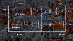
Figure 1 shows an isolated modulator. It’s essentially the same as a traditional delta-sigma modulator, but an isolation barrier separates the input and output circuitry.
The raw modulator stream passes to the output, which is often helpful for high-performance systems. The modulator bit stream can be fed to multiple sigma-delta filter modules (SDFMs) for different types of processing.
For example, it’s possible to feed a single isolated modulator’s output bit-stream to two different SDFMs. One SDFM can use a very low oversampling rate (OSR) that enables higher bandwidth and lower latency. This SDFM can be employed for transient detection and functional safety. Feeding the same modulator output bit stream to a second SDFM with a higher OSR results in a lower-bandwidth, higher-latency, and more precise measurement that can serve as feedback for the main control loop.
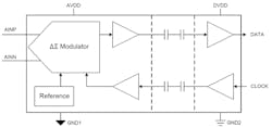
Similar to traditional non-isolated amplifiers, isolated amplifiers have an analog signal on the input and an analog signal on the output. Figure 2 shows an example block diagram for an isolated amplifier.
As with the isolated modulator, the input stage of an isolated amplifier consists of either a fully differential or single-ended input that drives a delta-sigma modulator. For isolated amplifiers, after the modulated output passes over the capacitive isolation barrier, the modulated output is then recovered, lowpass-filtered, and buffered to the output as a differential analog output signal.
Applications
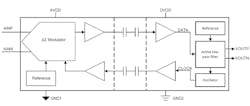
There are two common applications for isolated amplifiers and isolated modulators: voltage sensing and current sensing. An example implementation can be seen in Figure 3. Voltage sensing is typically performed using a resistor-divider circuit with an isolated amplifier, whereas current sensing is usually performed using an in-line shunt resistor and an isolated modulator. Both isolated amplifiers and isolated modulators can be utilized for either measurement, though.
Isolated amplifiers and isolated modulators are widely used in many industrial and automotive applications as part of voltage- and current-sensing systems to isolate two different voltage potentials from each other, as there can be large ground potential differences between the high- and low-voltage grounds. A direct connection between these two ground potentials will cause large currents to flow, resulting in equipment damage.
Equipment, such as an electric motor, injects large noise currents into the ground returns during operation, which can mix with the signal-path ground returns and interfere with measurement results. Isolated amplifiers and isolated modulators prevent the coupling of “noisy” and “clean” ground returns by breaking the ground returns with the isolation barrier.
Isolated amplifiers and isolated modulators can measure small voltages riding on very high common-mode voltage potentials while the output is still referenced to the low-side ground.
One important thing to keep in mind is the input impedance of the device. High-input-impedance (~1 MΩ) devices are meant for voltage sensing, while low-input-impedance devices (~20 kΩ) are meant for current sensing. Choosing a device with low input impedance for voltage sensing will often result in a significant offset error in the measurement.
Specifications
When choosing an isolated amplifier or isolated modulator, you must consider amplifier, modulator and isolation specifications. Here are a few definitions of some key terms to look for in the datasheet when selecting an isolated amplifier or isolated modulator:
Amplifier/modulator definitions:
- Input offset voltage is a differential input voltage that, when applied, forces the amplifier's output to 0 V. The offset voltage should be as small as possible to minimize the offset error in the measurement.
- Input offset drift quantifies how much the input offset voltage changes over temperature.
- Gain error is the percentage difference between the ideal gain and the measured gain.
- Gain error drift describes the changes in gain error over temperature.
- Isolation definitions:
- Isolation working voltage is the maximum voltage defined in the root-mean-square voltage that the isolated amplifier is able to handle continuously throughout its operating life.
- Isolation transient overvoltage is the voltage defined in the peak-to-peak voltage that the isolated amplifier can tolerate for 60 seconds.
- Common-mode transient immunity (CMTI) describes the maximum rate of change in ground potential difference that the isolated amplifier can withstand without errors.
Conclusion
Both isolated amplifiers and isolated modulators are an important part of a circuit designer’s component library. They enable safe monitoring of high-voltage circuits in harsh environments while protecting analog and digital measurement circuitry.
Isolated amplifiers and isolated modulators can perform similar functions, but some differences exist between them—most notably the integrated digital filter for the isolated amplifier and the flexible filtering options allowed by an isolated modulator.
When choosing an isolated amplifier or modulator, consider the input impedance of the device and pay close attention to the specifications explained in this article. Visit www.ti.com/isolation for more information or the TI E2E support forums if you have questions.
Alex Smith is an Applications Engineer at Texas Instruments.