
Add USB Type-C PD to Lithium-Ion Battery Packs
Universal Serial Bus Type-C (USB Type-C) provides high data-transfer rates and a reversible connector that the user can plug in without the need to check the orientation of a cable. Power Delivery (PD) is a specification that handles high power levels up to 100 W over USB. This is made possible by allowing voltages up to 20 V and currents up to 5 A.
USB Type-C PD combines the two technologies—high data transfer and high power—making it possible to quickly charge devices over a USB connection. In USB Type-C PD, the current can flow both ways from one device to another, with no set direction in the circuit, but purely depending on the devices communicating over the PD specification.
USB Type-C and PD provides a universal charging solution for devices such as laptops, phones, tablets, etc. and eliminates the need to carry bulky power supplies. This article presents solutions for adding USB Type-C PD to Li-ion battery packs.
While some major IC manufacturers offer solutions, few offer complete packages where everything that’s required for a complete USB-C PD solution is contained within a single IC. Vendors like Texas Instruments (TI), Cypress, Diodes Inc., ON Semi, and Analog Devices do offer ICs with the features needed to implement the complete solution.
This article describes various ways to retrofit USB Type-C PD to an existing battery pack that has full capability to charge, discharge, protect and gauge. The main components and their functionalities are:
- USB-C PD chip: This chip interfaces with the USB-C connector and connects to an external USB-C PD device over a USB Type-C connector. It handles all handshaking and power negotiation with the device and determines the power levels. This information is delivered to other chips in the board via control signals or I2C communication. The number of control lines used varies with different chips.
- Voltage regulator: This chip provides the required voltage for the USB Type-C VBUS, which has been negotiated by the USB Type-C PD chip. The voltage could be 5, 9, 15 or 20 V. Depending on the nominal voltage of the battery pack, the topology for the regulator could be buck, boost, or buck-boost. The power components used with the chip need to be selected to handle power up to 100 W. Some voltage regulators will interface with the USB Type-C chip over I2C and provide the required voltage. Others need to be set up in a way to provide the power as required by the USB Type-C chip. In applications where there’s a need to charge the battery pack over USB Type-C PD, the chip must be able to permit bidirectional current with the capability to regulate power in a constant-current/constant-voltage (CC/CV) algorithm to charge Li-ion cells.
It’s assumed that the basic protections and gauging are already provided in the battery pack by a battery-management system (BMS).
USB Type-C PD Chips
Various ICs are available; they differ in the way the negotiated voltage is communicated to the voltage regulator. Typically, this is accomplished in two ways:
Control Signals
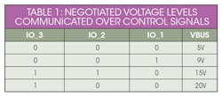
In this method, the chip detects and negotiates power with the devices and communicates the negotiated power levels via control signals. The negotiated power could be 5, 9, 15, or 20 V (Table 1). The chip also enables the power path to or from the battery pack.
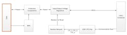
The number of control signals utilized varies with the chip. For chips that provide the negotiated power over control signals, a supporting voltage regulator is needed to take the state of control signals and generate the required voltage levels. Typically, this can be achieved with a voltage regulator that uses a feedback resistor to change the output voltage. A “resistor network” can be added between the USB Type-C PD chip and voltage regulation (Fig. 1).
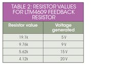
The role of the resistor network is to take the control signals from the USB Type-C PD chip and create equivalent resistance for the feedback resistor of voltage regulator. For example, assume you’re using the LTM4609 buck-boost regulator as the voltage regulator in a battery pack with nominal voltage of 16 V. Table 2 shows the resistor values that the resistor network must generate for the feedback resistor of the voltage regulator.
Examples of USB Type-C PD chips that generate control signals corresponding to the negotiated power are Cypress’s CCG2 family and TI’s TPS65987. The advantages with this approach are the wide range of voltage-regulator options and the ease in test and debugging. It does come with the disadvantage of having more components and requiring more space on the PCB.
I2C Interface
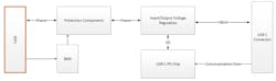
In this method, the USB Type-C PD chip provides the negotiated output voltage over I2C. A voltage regulator with an I2C interface can be paired with the USB Type-C PD chip to generate the required voltage level (Fig. 2).
Examples of this option are TI’s TPS65987D paired with its BQ25703 voltage regulator, and Cypress’s CCG2 paired with ON Semi’s NCP81239 voltage regulator. An advantage that they don’t need a resistor board, which means fewer components and reduced PCB space. The disadvantage is a smaller selection of voltage regulators and more difficulty in test and debug.
Selecting a bidirectional voltage regulator allows for charging and discharging of the battery pack. If you can’t find one for the application, separate voltage regulators could be used for charge and discharge paths.
Charging the Battery Pack over USB Type-C PD
To charge a Li-ion battery pack over USB Type-C PD, the voltage regulator used should be capable of regulating power in a CC/CV algorithm. Ideally, the USB Type-C PD chip is configured to negotiate 100 W (20 V, 5 A) from the connecting device. This minimizes the pack’s charging time. The regulator needs to be configured to provide an output voltage that’s equal to the charging voltage of the pack, which may involve bucking or boosting the power received from the power source.
Also, it may not be possible to charge the pack at 100 W due to the limitation of the charging current for the given cells. For example, assume the battery pack is a 1S9P combination using Samsung 18650 cells. The charging voltage for the pack is 4.2 V. To charge the pack over USB Type-C PD at 100 W, the regulator needs to buck down the input voltage from 20 V to 4.2 V, thus increasing the current flowing into the cells to around 24 A. The designer needs to select the regulator and its interfacing components to be able to carry the current. The same applies to the protection components such as the fuse, switches, and other components on the power path.
The charging current in this example should not exceed 2 A per cell as per the cell’s datasheet, resulting in a maximum charge current of only 18 A for the pack—less than the 24 V. This can be accomplished by limiting the output current of the regulator. The settings for overcharge current (OCC) and short-circuit charge (SCC) need to be adjusted accordingly so that the BMS doesn’t activate protections with the increased current flow.
Discharging the Battery Pack over USB Type-C PD
Care must be taken to make sure cell life isn’t adversely affected when an external device tries to draw high current from pack over USB Type-C PD. Let’s take the previous example of a 1S9P battery pack. If a device negotiates 20 V from the pack, the regulator boosts the pack voltage from 3.6 V (nominal) to 20 V. For the pack to provide 100 W, a current of 28 A needs to be drawn from the cells, which makes it around 3.1 A from each cell. This needs to be less than the maximum discharge current for the cells, which in this case is 8A as per the cell’s datasheet.
As previously mentioned, the components need to be chosen to allow for this level of current flow. The BMS settings for overcurrent discharge (OCD) and short-circuit discharge (SCD) need to be adjusted accordingly as well.
Summary
Multiple solutions are available for adding USB Type-C PD to battery packs. The chips mentioned in the article are suggestions—it’s up to the designer to make the right choice. The options vary in the components needed, complexity, and flexibility in IC selection. Carefully selecting the components, understanding the required interfaces, and integrating the components are the keys to have a working solution.
Anvin Joe Manadan is a Senior Electrical Engineer at Inventus Power.