
90-W Power over Ethernet Explained
Download this article in PDF format.
The new IEEE 802.3bt Power over Ethernet (PoE) standard allows standard Ethernet cables to carry up to 90 W of power, opening the doors to almost any Ethernet device being powered by a single Ethernet cable. Yet despite being in the market for over a decade, PoE technology is often shrouded in a cloud of mystery and confusion.
While the latest standard adds new features beyond increased power delivery, it is also more complex than previous standards. But take heart, this article will introduce you to PoE basics and some new features in the 802.3bt standard, as well as give you enough background to make complex PoE white papers, app notes, and datasheets understandable.
The PoE Connection
“Being powerful is like being a lady. If you have to tell people you are, you aren't.” —Margaret Thatcher
On the surface, PoE sounds complex: Inject high power onto a cable designed for data without disrupting the high-speed traffic the cable is carrying. Fortunately, the Ethernet standard and the cable design greatly simplify this technology. As shown in Figure 1, inside the Ethernet cable itself are four twisted pairs of wires. Ethernet is an isolated network, so each twisted pair connects to a transformer. All PoE does is inject a dc voltage (~54 V) onto the twisted pairs of the Ethernet cable through center taps on the transformers.

In a two-pair power configuration (802.3af, 802.3at), one twisted pair is positive and the other is negative. In a four-pair power configuration (802.3bt), two twisted pairs are positive and two are negative. The power-sourcing equipment (PSE) is the device putting power onto the cable, and the powered device (PD) is the device taking power off of the cable.
Finally, the PoE standards enable the PSE to power the twisted pairs in either polarity. Therefore, the PD must have input bridges (diodes or FETs) to set the polarity of the incoming power.
Detection
“Eighty percent of success is showing up.” —Woody Allen
Now we know how to put power onto the Ethernet cable, so the PSE can just blast power down the cable whenever something is connected, right? Wrong! Applying power to a non-PoE device can damage it. PoE starts with a detection phase in which the PSE determines if the connected device is a PD requesting power. The PSE applies two voltages between 2.7 and 10.1 V onto the Ethernet cable, and the PD presents a 25-kΩ resistance, signaling to the PSE that a valid PD is connected (Fig. 2).

Classification
“Never sacrifice your class to someone who has none.” —Unknown
Once a valid PD is detected, the PSE and PD then do an analog handshake known as “classification,” in which the PD requests a power “class” and the PSE then tells the PD what class is granted. PoE technology uses the terms type and class when discussing power. Type simply denotes the kind of analog handshake from the PSE. Class defines the maximum power the PSE will put onto the cable and the maximum power the PD can draw from the cable. Because PoE follows the Ethernet standard, the cable can be up to 100 meters in length, so a fair amount of power is lost in the cable. The table lists the various PoE types and classes.

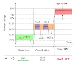
Let’s start with the simplest classification handshake, type 1 (Fig. 3). The PSE puts 15.5-20.5 V onto the cable and measures the PD’s current draw. Due to cable loss, the PD will see 14.5-20.5 V from the PSE during classification. Based on the PD’s current draw, the PSE determines the PD’s requested class and either powers it on or, if the PSE doesn’t have sufficient power, doesn’t apply power.

The amount of current drawn by the PD during classification is, confusingly enough, referred to as the classification signature or classification current. 802.3bt defines five classification signatures the PD can draw during classification.
Type 2 builds on type 1 by adding a second classification pulse (Fig. 4). During classification, the PD draws 40 mA (classification signature 4) to signal class 4 to the PSE. A type 1 PSE simply sees this as a request for class 3 power and proceeds to power the PD. A type 2 PSE responds to the higher current by lowering the classification voltage to a “mark” voltage to create a pulse. It then repeats this procedure to create a second classification pulse and powers the PD. The two classification pulses signal to the PD that class 4 power has been granted by the PSE.
Here’s where you come in as the PD designer. A PD requesting class 4 might not get it from the PSE. It might receive less than it asked for through “power demotion,” and your design will need to make do with less power. Keep reading—we will get there in a few more paragraphs.
Now the moment you’ve been waiting for: 802.3bt classification (Fig. 5). As you might have guessed, it’s very similar to type 1 and 2; it just adds more classification pulses. Type 3 increases the number of classification pulses to four, and type 4 uses five pulses.
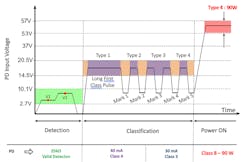
When a PD requests type 3 or 4 power, it draws 40 mA (classification signature 4 current) for the first two pulses and then lowers its current draw to the classification signature 3, 2, 1, or 0 level for the subsequent pulses. The lower current tells the PSE how much power the PD is requesting. In fact, after the third pulse, the PSE has determined how much power the PD wants, and the additional pulses simply tell the PD how much power is being granted by the PSE.
If the PSE generates four classification pulses, then the PD is granted type 3 power. Five classification pulses signal the PSE granting type 4 power to the PD. In other words, if the PD asked for class 7 or 8 power and the PSE grants type 4, then the PD gets the power it requested. Likewise, if the PD requests class 5 or 6 and the PSE grants type 3, then the PD receives the power it requested. With this information, you now know the key aspects of 802.3bt PoE classification.
But wait, what’s this long first classification pulse, you might ask? And what happens if the PSE doesn’t grant the PD the power it requests? Hold that thought, we will get there shortly.
Power Demotion
“Tact is the ability to tell someone to go to hell in such a way that they look forward to the trip.” —Winston Churchill
Most PoE-enabled Ethernet switches don’t have enough power capacity for full power on each PoE Ethernet port, especially at 90 W per port, which adds up quickly. The PoE standard provides a simple way for the PSE to still power a PD but with less power than the PD requested—this is called power demotion. When a PSE demotes a PD, it assigns it a lower type than the PD requests. Because PSEs can only assign type to a PD, when a PD is demoted to a lower type, it’s automatically assigned the highest power level within that type. Let’s look at two examples of how this works.
Example 1: A PD requests class 8 power, but the PSE only has class 6 power available. In this scenario, the PSE demotes the PD to type 3, and the PD receives class 6 power.

Example 2: A PD requests class 8 power, but the PSE only has class 5 power available. Because the PSE can only demote the PD by type, it can’t assign the PD class 5 power. If it granted the PD type 3 power, the PD would be assigned class 6 power. Instead, it must demote the PD to class 4, type 2 power.

As a system designer, you understand what’s important here is to recognize the different power demotion options available to the PSE based on the class the PD is requesting. A class 8 PD may be demoted to class 6, class 4, and class 3 power. To ensure full compatibility, the PD system needs to operate at all four power levels. Otherwise the PSE will shut down the connected PD for drawing too much power. Most PD devices on the market include some method for communicating the received type back to the main PD system controller, such as two digital pins or a comm port.
Power On
“The measure of a man is what he does with power.” —Plato
Power on is the final stage of a PD receiving power. The IEEE PoE spec includes the inrush current that a PD may draw during power up. Most modern PD devices include built-in inrush current limiting. All the designer needs to do is follow the PD device’s recommended input capacitance and let it take care of the rest.
Maintain Power Signature
“Power does not corrupt. Fear corrupts. Perhaps the fear of a loss of power.” —John Steinbeck
The previous PoE standards include the concept of Maintain Power Signature (MPS). If a PD draws less than 10 mA of current, the PSE disconnects the PD. The MPS feature enables the PD to draw short pulses of current to maintain the connection to the PSE when the PD system is in a low-power state.
The new 802.3bt standard introduces a shorter MPS pulse to maintain the PSE connection, allowing PDs to enter an even lower-power state. Remember the long first class pulse from the type 3 or 4 PSE? This signals to the connected PD that the PSE supports short MPS, and the PD may use short MPS pulses to maintain the connection.
Just like with inrush, most 802.3bt PDs automatically switch to short MPS when connected to a PSE that supports the feature. Short MPS allows the system to enter a lower-power state than with previous PoE standards.
Autoclass, LLDP, and Closing Thoughts
“You must never try to make all the money that’s in a deal. Let the other fellow make some money too, because if you have a reputation for always making all the money, you won’t have many deals.” —J. Paul Getty
There’s one last new feature in the 802.3bt standard worth mentioning—autoclass. With autoclass, a PD draws the maximum power it will ever consume shortly after power up. This allows the PSE to measure the actual power the PD will consume and adjust power allocation accordingly. A PD may request class 8 (90 W) of power, but in reality, only draw 80 W. With autoclass, the PSE can measure this and then have 10 W of power to provide to other PDs in the system.
Another advanced feature of PoE is the Link Layer Discovery Protocol (LLDP). Ethernet networks have used LLDP for years to enable switches and routers to discover various details using the data layer. PoE adds an extension to LLDP for the PSE and PD to also communicate information over the data layer. For example, LLDP allows the PSE and PD to renegotiate power in one-tenth-of-a-watt increments, possibly freeing up power for the PSE or granting the PD slightly more power.
The 802.3bt standard brings unprecedented levels of both literal and figurative power to PoE system designers. In addition, it delivers several useful new features, such as short MPS, that bring more flexibility to PoE connected systems. With the ubiquitous nature of Ethernet networks and the higher power of 802.3bt PoE, more and more systems will take advantage of this technology to eliminate external power supplies.
Charlie Ice is Senior Product Manager, PoE Products, at Silicon Labs.