Shrinking Power Supplies and Maximizing Efficiency in High-Voltage Systems
Members can download this article in PDF format.
If a power supply could convert all of the power it’s receiving into usable power output, it would be 100% efficient. However, energy loss is an unavoidable part of energy-conversion systems, so a certain amount of energy is “lost” during each conversation stage as you convert from one voltage level to another. Typically, this is expressed as a percentage. A well-designed power supply can achieve efficiencies that approach the mid to high 90s.
The power supply should be as small as possible to save space or leave room for added system functions. To be truly useful, an integrated power and signal solution must not only offer high efficiency and high power delivery, but also high isolation performance and low emissions.
Electronic isolation is a means of preventing the transfer of direct current (dc) and unwanted alternating current (ac) between two parts of a system while still enabling signal and power transfer between those two parts. It’s the ability to couple one circuit to another without the use of direct wire connections.
It doesn’t matter that the common-mode voltage is dc; it could be ac, even at a different frequency. Isolation blocks unwanted dc and ac currents between separate parts of a system while transferring desired signals and/or power. This kind of isolation is required in a number of applications, including industrial equipment such as programmable logic controllers (PLCs), motor drives, solar inverters, and electrical vehicles (EVs).
Sponsored Resources:
- Fundamentals of EMI Requirements for an Isolated DC/DC Converter
- Power Through the Isolation Barrier: The Landscape of Isolated DC/DC Bias Power Supplies
- Isolation 101: How to find the right isolation solution for your application
Isolation Implementation
The landscape of isolated dc-dc bias power supplies has changed, giving electronic designers more options to move signals and power across an isolation barrier. Isolation might be required for safety, noise immunity, or large potential differences between system domains. Isolation is used in a wide variety of applications: to protect human operators and low-voltage circuitry from high voltages, to improve noise immunity, and to handle ground potential differences between communicating subsystems.
Another application example is the need to isolate one system from another while providing communications between the two. Automotive applications with Controller Area Network (CAN) or CAN Flexible Data-Rate (FD) protocol communications can isolate these signals from the high-voltage side of the automobile using an isolated CAN transceiver that integrates isolation and transceiver components.
One method of electrical isolation is to use a transformer. The primary and secondary windings are electrically separate, and power transfer is strictly by way of magnetic induction rather than current flow.
Levels of Isolation
Different levels of isolation exist, including functional, basic, double, and reinforced isolation.
Functional isolation passes a signal or power from a system at one voltage potential to another system and a different voltage. It doesn’t protect against electrical shock. Basic isolation is functional isolation, but adds electrical shock protection. Class I devices use functional isolation along with an earth ground connection to protect users.
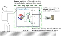
Double isolation takes a system with basic isolation and adds a supplementary insulation layer between the electrical parts and the end user to reduce the likelihood of electrical shock if basic isolation fails. Class II products, manufactured with ac plugs that don’t have the earth ground prong on them, require double isolation (Fig. 1).
Such isolation improves the safety of the product because it doesn’t depend on external wiring for user safety. Examples of end equipment with double isolation include grid asset monitoring systems, portable medical devices like IV pumps, and electrical devices such as blenders or charging supplies for cellphones.
Reinforced isolation achieves the same result as double isolation using a single layer. A device with reinforced isolation provides basic isolation. Furthermore, it’s designed to ensure physical separation between printed-circuit-board (PCB) traces, cores, windings, pins, etc., while meeting safety creepage and clearance distances (which refer to a physical distance between two voltage systems).
Handling EMI
Understanding how to manage and reduce emissions is crucial to the performance of your power-supply design. Electromagnetic interference (EMI) is any random unwanted broadband signals intentionally or unintentionally generated by electronic equipment.
There two types of EMI. Conducted EMI is transferred from the source to another device through electrical conduction in wiring. Radiated EMI consists of both electric and magnetic fields that are transmitted over a distance. It could also be capacitive coupling between wires in a cable or components on a PCB. In addition, the radiated transfer may be derived through induction; for example, 60-Hz power lines induce voltage in anything nearby that will carry current.
Overcoming EMI is one of the biggest challenges that engineers face today. EMI can cause problems to neighboring electrical circuitry if not managed and properly reduced below the sensitivity level of nearby circuitry. Industry standards from bodies such as Comité International Spécial des Perturbations Radioélectriques (CISPR), the International Electrotechnical Commission, Comité Européen de Normalisation Électrotechnique, the Federal Communications Commission, and the United States Military Standard help regulate and alleviate EMI so that circuits can coxeist with each other.
In a switch-mode power supply, the noise source often refers to noise generated from switching operations. When the powered device turns on and off, the external current from the power loop charges or discharges the parasitic capacitors. The voltage (dV/dt) or current (di/dt) slew rates will be high when the switching speed is very fast. The common-mode noise current flows through the parasitic capacitor between the drain of the power metal-oxide semiconductor field-effect transistor (MOSFET) or collector of the insulated gate bipolar transistor (IGBT) and the heatsink. The return path can be earth ground and back to the power stage, which is an example of a conductive EMI path.
Easy to Use
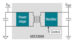
Fully integrated, reinforced solutions are available in small packages. For example, Texas Instruments’ UCC12050 integrates all of the control, drivers, field-effect transistors, and magnetics into a single package (Fig. 2). The engineer need only place the device on the board with some bypass capacitors and follow the directions for proper board layout to design a reinforced isolated solution to bias supply applications in a small footprint. All of the engineering work has been done—no magnetics design, no supply controller selection.
Its 2.65-mm height enables designers to reduce their solution volume by as much as 80% compared to discrete solutions and 60% compared to power modules—with twice the efficiency of competing products, according to TI. It only requires input and output capacitors. The UCC12050 is rated for 5 V with a +10% input and delivers an isolated 3.3-, 3.7-, 5-, or 5.4-V output. The device has reinforced isolation, and its sister product, the UCC12040, is rated for basic isolation.
TI designed the UCC12050 isolated dc-dc module with EMI control in mind, meeting radiated and conducted emissions per the CISPR 32 standard without requiring ferrite beads, saving board space and cost. The switching frequency is much higher compared to power modules, allowing for significant height and weight reduction versus lower switching-frequency alternatives. The internal topology control scheme runs closed-loop without an LDO or external feedback components.
The device is rated for reinforced isolation of 5 kVrms and a 1.2-kVrms working voltage, and will operate at a 125°C ambient temperature. The aforementioned UCC12040 is rated for basic isolation of 3 kVrms and a 800-Vrms working voltage.
Sponsored Resources:


