Battery-Cell Charging Basics
Members can download this article in PDF format.
What you'll learn:
- Specifics of the charging and discharging steps of a cell charger/discharger.
- How to achieve regulation via feedback.
- A look at the 4-wire connection to the cell.
Charging and discharging are the most fundamental actions applied to cells by cell researchers, cell manufacturing engineers, and battery-pack designers. In this article, I will cover the basics of how a cell charger/discharger functions. I also will touch on how contacting the cell through its fixture is an important part of successful charging and discharging.
Typically, a lithium-ion cell is charged using a constant-current/constant-voltage (CC/CV) charging step. During discharge, a constant-current (CC) discharge step is most often used. How does a charger achieve CC/CV, or a discharger achieve CC?
If we look at basic electronics, a charger is a power supply, very similar in design to any simple benchtop power supply you have encountered in an electronics lab. A power supply allows the user to set a voltage operating point, which is sometimes called the voltage limit or constant-voltage (CV) setpoint. If the power supply is a CV/CC-type supply, then the user also can set the current limit or CC setpoint.
The power supply is basically a regulated power amplifier. Regulated means it uses a feedback system to monitor operation and continuously adjust output to maintain the controlled parameter at the user setpoint.
Deep Dive into a Charging Step
When trying to perform a CC/CV charging step, the charging process instruction might be “Charge at 3 Amperes until the voltage reaches 4.2 V, then charge at 4.2 V until the current drops off to 10 mA.”
The user will need to set the current limit to a CC charging value of 3 A and a voltage limit with the CV charging value of 4.2 V. (We’ll cover the 10-mA cutoff a bit later.) The user might not realize this is what’s being programmed down to the charger hardware. It’s because the battery charger hardware may be controlled from a high-level software interface that accepts more human-friendly charging process instructions.
Now, the charging begins. If the state of charge (SoC) of the cell is low, the cell’s open circuit voltage (OCV) will be low, perhaps 2.5 V. The power-supply circuit in the charger will try to regulate the voltage to be 4.2 V at the cell, but the cell voltage is below 4.2 V. The circuit will start to pump current into the cell to drive up the voltage, but the cell’s OCV will remain low because the cell is at a low SoC. Subsequently, it will pump more and more current into the cell while the cell’s OCV remains low.
Eventually, the power-supply circuit will hit the user-programmed current limit of 3 A. When this happens, the circuit will switch to CC mode and regulate the current at the user-programmed value of 3 A. In CC mode, the power-supply circuit will not try to regulate the voltage anymore because when in CC mode, current is the controlled parameter and the voltage isn’t controlled, allowing the voltage to change based on what’s happening in the cell. All of this occurs in milliseconds.
Continuing, the cell will charge in CC. As current flows into the cell, energy is stored in the cell and the SoC of the cell rises. As the SoC rises, so does the OCV. Eventually, the OCV will increase to the user-programmed voltage limit of 4.2 V. When this happens, the power-supply circuit will switch to CV mode and then regulate the cell’s OCV at the desired voltage. Once again, this switchover from CC to CV, which is typically called mode crossover, happens in milliseconds.
In CV mode, the power-supply circuit will not try to regulate the current anymore because voltage is the controlled parameter. While the voltage is held constant, the current will begin to drop as the cell reaches 100% SoC and the cell can no longer accept more energy. Eventually, the cell current will tail off down to the 10-mA cutoff value. The overall charger control system will then decide to stop charging because the user-requested 10-mA cutoff has been reached.
Regulation through Feedback
The power-supply circuit must know the voltage at the cell; thus, it measures the voltage at the cell via voltage-monitoring pins. (More on voltage-monitoring pins later.) When operating in CV, the voltage is measured and fed back into the power-supply circuit. The feedback system takes the measured voltage and compares it against the user-programmed voltage setpoint, making up/down adjustments to the power-supply voltage to maintain or regulate the correct voltage at the cell. Hence, voltage is the controlled parameter when in CV and the current isn’t controlled, so it changes based on what’s happening in the cell.
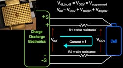
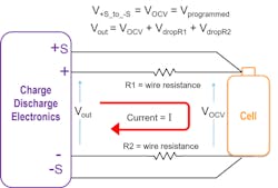
Note that the output of the power-supply charger circuit will be higher than the OCV of the cell at the end of the wires due to voltage drop in the wires between the output of the charger and the cell terminals (Fig. 1). For additional information, check out this article.
1. Voltage drops VdropR1 and VdropR2 due to current flowing through wire resistances R1 and R2 complicate cell charging.
The charge/discharge electronics measure the cell OCV at terminals +S and -S, which have high input impedance. As a high-impedance input, no current flows into these terminals through the sensing wires. Therefore, the resistance of these wires is irrelevant. The result is that voltage drops, and the current-carrying wires are compensated out. Why? Because the electronics can measure the cell’s OCV and regulate Vout to overcome the voltage drops in the wires by raising the charger output voltage to maintain the cell OCV at the end of the current-carrying wires.
Likewise, the power-supply circuit must know the current flowing to the cell during CC mode. The circuit measures the current to the cell via an internal current-measurement sensor. There’s no need for current-monitoring pins because the current flow is the same everywhere in the current loop, which contrasts with voltage, where you encounter a voltage drop due to resistance in the wires.
When operating in CC, the current is measured and fed back into the power-supply circuit. The feedback system takes the measured current and compares it against the user-programmed current setpoint and regulates the power-supply current output up/down to maintain the correct current to the cell. Hence, current is the controlled parameter when in CC and the voltage isn’t controlled, allowing the voltage to change based on what’s happening in the cell.
A final nuance here: What this all means is you can’t say “I want to charge the cell in CC,” as the charger operating mode isn’t directly controlled. The cell determines if the power-supply charger circuit operates in CV or CC. If the cell OCV is less than the charger voltage setpoint, the charger will be in CC. If the cell OCV is at the charger voltage setpoint, then the charger will be in CV.
On to the Discharging Step
For a discharging step, the charging process instruction might be “Discharge at 6 Amperes for 60 minutes.” As in the previous example, the user may provide this instruction to some high-level software. Ultimately, though, this will result in programming the discharger hardware to act like an electronic load to pull current from the cell.
Normally, discharge is completed with the cell starting at a high SoC% and the cell’s OCV will be high as well. The discharger circuit is probably the same electronics as the charging circuit, and it will likely support CC and CV operating modes. Fundamentally, the power circuit is a combination circuit that can act as a CV/CC power supply sourcing energy into the cell during charge, and as a CV/CC electronic load absorbing energy from the cell during discharge.
So, by requesting CC discharge at 6 A for 60 minutes, the user’s request will be translated by the system software into programming the electronic load circuit with a CC setpoint of 6 A and the constant voltage setpoint to be very low, perhaps 1 V. The system will automatically set this voltage point to be so low that it’s never achieved, as you will see in the following paragraphs.
Now, the discharging begins. Generally, you will want to discharge the cell when the SoC of the cell is high, making the cell’s OCV also high, perhaps 4.2 V. The electronic load circuit in the discharger will try to regulate the voltage to be 1 V at the cell, but the cell voltage is measured by the voltage measurement pins to be 4.2 V. The electronic load circuit will start to draw current from the cell to pull down the voltage, but the cell’s OCV will remain high because the cell has sufficient stored energy while at a high SoC. The electronic load will draw more and more current from the cell while the cell’s OCV still remains high.
Eventually, the electronic load circuit will hit the user-programmed current limit of 6 A. When this happens, the circuit will switch to CC mode and regulate the current at the user-programmed value of 6 A. In CC mode, the electronic circuit will not try to regulate the voltage anymore because when in CC mode, current is the controlled parameter. All of this happens in milliseconds.
The electronic load continues to draw stored energy from the cell, lowering the cell’s SoC and OCV. For the duration of the discharge, the cell’s OCV never reaches the very low programmed voltage limit. Therefore, the electronic load stays in CC for the entire discharge step as requested by the user. The overall charger control system will then decide to stop the discharging step because the user-requested 60-minute cutoff has been reached.
Contacting the Cells
High-quality charger/dischargers will utilize a 4-wire connection to the cell. The current will flow through two current-carrying wires, (+) plus and (−) minus, sized to handle the maximum current of the cell. The other two wires are for measuring the voltage at the cell so that the charger/discharger gets the required feedback for proper constant voltage regulation.
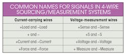
These wires, known as the remote-sense wires, are only for voltage measurement, so no current flows through them. Thus, sense wires and associated contact pins can be thin. See the table for common names used by these 4-wires.
The current-carrying wires will contact the cells through appropriately sized current contacts. Depending on the current, these could be relatively thin pins carrying a few amperes, or they could be large contact blocks with a large contact area that makes a very low resistance contact of milliohms or microhms.
In contrast, the remote-sense voltage-measurement pins can be small contact points at the end of thin wires, as their resistance isn’t critical because no current flows through these pins or through the sense wires.
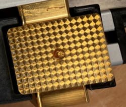
Whether high current or low current, contacts are often designed with a sharp edge or point to break through oxide layers that may build up on the cell terminal contacts. Because these oxide layers will increase the contact resistance, they will need to be pierced by the sharpness of the contact. Such pins are often plated with brass or gold to avoid oxide buildup on the pin itself.
Many pin designs are coaxial with the sense pin inside of, yet not in electrical contact with, an outer, tubular, high-current pin. In the case of a large contact plate, the sense pin is sometimes located inside a center hole in the contact plate (Fig. 2).
2. Shown is the surface of a high-current contact block with the center voltage sense pin. The pyramid shapes are pointed to break through the oxide layer. (Photo courtesy of VoltaVision GmbH)


