Sugar isn’t so Bad: Fuel-Cell Patch Harvests Body’s Glucose
What You’ll Learn:
- How a unique ceramic substrate and glucose were combined to create a flexible biocompatible battery.
- The sophisticated fixturing built for single-unit and “volume” testing.
- Typical and peak results across the multiple devices.
Powering devices within the body presents a dilemma: A discrete battery can provide the power but presents size and safety challenges, while an RF-based approach has both power and depth limitations. At the same time, we know that too much sugar can be bad for your health, but it’s also an essential and available nutrient in the body.
Now, researchers at MIT, the Swiss Federal Institute of Technology (EPFL – Lausanne), and Eidgenössische Technische Hochschule (ETH – Zurich) have designed a new type of fuel cell that converts in-body glucose directly into electricity. The cells are just 400 nm thick and generate about 43 µW per square centimeter, which the researchers maintain is the highest power density of any glucose fuel cell to date under ambient conditions. They can withstand temperatures up to 600°C, well beyond the level needed remain stable through the high-temperature sterilization process required for all implantable devices.
The heart of the new device is a ceramic base that retains its electrochemical properties even at high temperatures and miniature scaling-down. Although we normally think of ceramics as brittle, at this thickness the battery could be fabricated as an ultra-thin film or coating, then wrapped around implants to passively power electronics using the body’s abundant glucose supply.
Layered Design
The design consists of three layers: a top anode, a middle electrolyte, and a bottom cathode. The anode reacts with glucose in bodily fluids, transforming the sugar into gluconic acid. This electrochemical conversion releases a pair of protons and a pair of electrons.
The middle electrolyte acts to separate the protons from the electrons, conducting the protons through the fuel cell, where they combine with air to form molecules of water—a harmless byproduct that flows away with the body’s fluid. Meanwhile, the isolated electrons flow to an external circuit, where they can be used to power an electronic device (Fig. 1).
1. Schematic of glucose fuel cell, chip, and individual device: (a) Schematic of a ceramic glucose fuel cell based on a freestanding membrane of a porous Pt anode/CeO2 electrolyte/dense Pt cathode. (b) Optical photograph of fuel-cell chip containing 30 individual glucose-fuel-cell devices. (c) Optical microscopy image of an individual freestanding ceria membrane.
The researchers used an electrolyte made from ceria, a ceramic material with high ion conductivity, is mechanically robust, and is widely used as an electrolyte in hydrogen fuel cells. In addition, it’s biocompatible, a necessity for the target application. The team sandwiched the electrolyte with an anode and cathode made of platinum, a stable material that readily reacts with glucose.
They fabricated 150 individual glucose fuel cells on a chip, each about 400 nm thin and about 300 µm wide. They patterned the cells onto silicon wafers, showing that the devices can be paired with a common semiconductor material and processes.
In other glucose-based designs, the electrolyte layer is often made from polymers. However, polymer properties, including their ability to conduct protons, will easily degrade at high temperatures. Moreover, they’re difficult to retain when scaled down to the dimension of nanometers and are hard to sterilize.
Tests Assess, Verify Performance
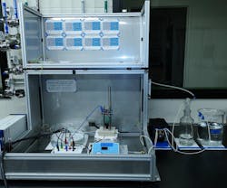
Basic testing began with a single-station station arrangement (Fig. 2). They found many cells produced a peak voltage of about 80 mV. Given the tiny size of each cell, this output is the highest power density of any existing glucose fuel-cell design.
2. The full measurement setup includes a custom-designed fuel-cell flow case and liquid/gas handling systems.
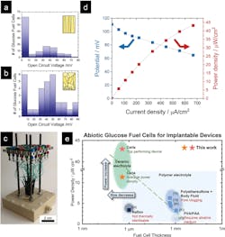
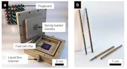
They realized a high degree of statistical verification of successful fabrication and electrochemical function by evaluating 150 devices for open-circuit voltage performance and 12 devices for power density. Current produced by each cell was measured as the researchers flowed a solution of glucose over each wafer in a custom-fabricated test station with spring-loaded contacts (Figs. 3 and 4).
3. Performance and comparison of ceramic glucose fuel cells: (a,b) Histograms of the open-circuit potentials of 120 ceramic glucose fuel cells with dense ceria electrolyte (a) and 30 ceramic glucose fuel cells with porous ceria electrolyte (b). (c) Test setup allowing for rapid screening of 30 individual glucose fuel-cell devices through spring-loaded needles and plug board. (d) Polarization curve of a ceramic glucose fuel cell, exhibiting a peak power density of 43 µW/cm2. (e) Comparison of previously reported polymer-electrolyte-based glucose fuel cells with those in this work, i.e., ceramic-electrolyte glucose fuel cells: power density as a function of fuel-cell thickness. The ceramic glucose fuel cells show 3X higher miniaturization and higher power densities than existing abiotic glucose fuel cells.
4. (a) Photograph of the opened test setup allowing for rapid screening of 30 individual glucose fuel-cell devices through spring-loaded needles and plug board. (b) Magnified photograph of spring-loaded needles for reproducible contact of the glucose fuel-cell devices.
Their data-acquisition system recorded basic performance and other factors over time (Fig. 5).
5. (a) Example of a raw time profile of fuel-cell voltage and current density over the course of more than 10 hours. (b) Voltage and power density as a function of time for the record-performing glucose fuel cell. The data corresponds to the top-performing glucose fuel cell as reported.
As this project was done at MIT, testing didn’t begin or end with just basic voltage, current, and power parameters. For example, they used Raman scattering, X-ray diffraction, and scanning electron microscopy (SEM) to analyze the ceramic base material for consistency and structure. They also assessed endurance and other factors using electrochemical impedance spectroscopy and performed post-mortem analysis of glucose fuel-cell membrane devices via optical microscopy and SEM.
“Instead of using a battery, which can take up 90% of an implant’s volume, you could make a device with a thin film, and you’d have a power source with no volumetric footprint,” said Jennifer L.M. Rupp, thesis supervisor for team leader and PhD candidate Philipp Simons, who developed the design as part of his PhD thesis in MIT’s Department of Materials Science and Engineering (DMSE). “Excitingly, we are able to draw power and current that’s sufficient to power implantable devices,” added Simons.
The work, including device-fabrication details, is covered in their lengthy paper “A Ceramic-Electrolyte Glucose Fuel Cell for Implantable Electronics” published in Advanced Materials, and is enhanced by a slightly shorter “Supporting Information” posting.


