16 Ways to Design a Switch-Mode Power Supply

This article is part of TechXchange: Power Supply Design
Download this article in PDF format.
Simply put, designing a power supply is a major undertaking. After making your build vs. buy decision, you face a myriad of circuit choices—more than you probably realize. Building a power supply used to be relatively straightforward, but with switch-mode methods dominating these days, it has become a complex specialty. If you’re not a power-supply expert and/or this is one of your first designs, you may need some guidance. The information presented here should help you identify your options and zero in on one to follow through with.
Step 1: A Good Specification
It all begins with a good specification. It’s critical to take the time to research your needs and write a detailed specification. As a starting point, list the following key features:
- Input-voltage (ac or dc) range
- Output voltages (dc or ac) and tolerances
- Output-current requirements
- Ripple maximum
- Estimated total power required
- Efficiency requirements, if any
- Electromagnetic-interference (EMI) considerations, if any
Step 2: A First Decision
With these specifications, you should be able to make your first big choice: linear vs. switch-mode design. Yes, linear supplies are still an option even in the current switch-mode dominant environment. If your design can accept the lower efficiency of a linear supply, you may appreciate its benefits. The major advantages of a linear supply are simplicity of design, lower cost, abundant relevant components, proven techniques, and low EMI emissions.
On the other hand, switch-mode designs are inherently noisy, and the circuits you’re powering may be susceptible to that noise. For example, an oscillator, clock, synthesizer, or other critical circuit may require low phase noise or jitter. A linear supply with a low-dropout (LDO) regulator would provide a clean dc to meet that need. At least keep the linear option in mind, as it may still be your best choice in some designs.
Most new designs are of the switch-mode variety. The advantages of a switch-mode power supply (SMPS) are just too great to ignore. Efficiency is the primary benefit, with efficiencies over 90% for many designs. Small size and reasonable cost are other benefits. The downside is complex and tricky design with many alternative approaches. You can make a more informed design choice, though, if you expand your specifications list.
Step 3: Expanded Specifications
In addition to the basic specifications compiled earlier, these should also be defined for your design:
- Requirement for electrical isolation between input and output
- Temperature range of operation
- Expected in-rush current
- Peak and average output current
- Transient exposure and response needs
- Load- and line-regulation requirements
- Switching frequency
- In addition to EMI needs, include the need for power factor correction (PFC), Underwriters Laboratories (UL), or other certifications
Step 4: Choose a Topology
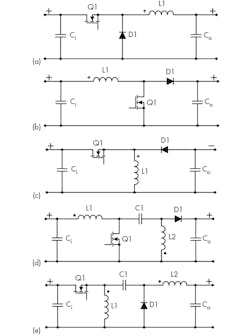
The most popular dc-dc SMPS topologies are buck (a), boost (b), inverting buck-boost (c), SEPIC (d), and Zeta (e). The MOSFET does the switching, the inductors and capacitors store energy, and the diode controls the direction of current.
You may already know that several different switch-mode circuit designs are available. But did you know there are actually 16 topologies that you should be aware of? One of these is sure to fit your needs:
- Buck
- Synchronous buck
- Boost
- Inverting buck-boost
- SEPIC
- Cuk
- Zeta
- Fly-buck
- Flyback
- Two-switch flyback
- Active-clamp forward
- Single-switch forward
- Two-switch forward
- Half-bridge
- Full bridge
- Phase-shifted full bridge
Lack of space here prevents full coverage. However, there are two great sources you can explore to evaluate your topology choices:
- Power Topolgies Quick Reference Guide: These nine pages provide a quick refresher on the most common switching power-supply topologies. It’s filled with relevant waveforms and equations.
- More details are available in the 200-page Power Topologies Handbook. Circuit explanations and design recommendations are based upon requirements.
Step 5: Begin Your Design
A typical approach is to narrow your choices of topology before making a final decision. The most popular topologies are buck, boost, buck-boost (and inverting version), SEPIC, and Zeta. Figure 1 shows the simplified circuits for each. The buck format steps down the input voltage while the boost steps it up. The other three can do either. The Cuk topology is a good one if you need to change the output’s polarity.
If you need some isolation, transformers can be employed. Topologies that will incorporate them in the design are flyback, clamp forward, push-pull, half bridge, or full bridge.
As for switching frequency, it usually comes down to the best estimate based on your application. Today, typical switching frequencies range from about 100 kHz to several megahertz. Low frequencies are generally better for higher-power applications requiring best efficiency. Higher frequencies make filtering easier with smaller capacitors and inductors, and can lead to reductions in both size and cost.
Also be sure to consider the impact of the fundamental and harmonics on other equipment nearby. One potential solution to limit switching EMI is dithering. That involves the random variation of the switching frequency to reduce any EMI by spreading out the spectrum over a wider range.
Switch-mode power-supply design can be a mysterious enterprise if you don’t know how or where to start. Check out this recommended blog to better understand how to select the most fitting power-supply topology for your application.
Step 6: Other Resources
Diodes and integrated circuits are at the heart of your design. Keep in mind that most semiconductor companies have support products or services, such as online design software like Texas Instruments’ WEBENCH. Don’t forget the possibility of reference designs and evaluation kits to further speed up and simplify your design.
Read more articles in TechXchange: Power Supply Design
About the Author

Lou Frenzel
Technical Contributing Editor
Lou Frenzel is a Contributing Technology Editor for Electronic Design Magazine where he writes articles and the blog Communique and other online material on the wireless, networking, and communications sectors. Lou interviews executives and engineers, attends conferences, and researches multiple areas. Lou has been writing in some capacity for ED since 2000.
Lou has 25+ years experience in the electronics industry as an engineer and manager. He has held VP level positions with Heathkit, McGraw Hill, and has 9 years of college teaching experience. Lou holds a bachelor’s degree from the University of Houston and a master’s degree from the University of Maryland. He is author of 28 books on computer and electronic subjects and lives in Bulverde, TX with his wife Joan. His website is www.loufrenzel.com.
Comment About the Article
To join the conversation, and become an exclusive member of Electronic Design, create an account today!

Leaders relevant to this article: