This article is part of TechXchange: Power Supply Design
This file type includes high resolution graphics and schematics when applicable.
Switching power supplies are inevitable in today’s designs. They’re power-efficient and thermal-efficient, with various schemes available for every application. Switching regulators solve the power dissipation and efficiency problem by operating via pulse-width modulation (PWM). There are multiple considerations when designing the switching power supply circuit, though, and price shouldn’t be the only driver for the component selection. A complete understanding of all these elements will help you select the most cost-effective part for your design.
Power Output
The voltage and nominal current required at the output of the switching dc-dc stage is the most obvious factor to consider in the design. Datasheets only tell part of the story. Don’t take their stated output capabilities for granted! In fact, you might want to calculate the maximum output power you might need from the switching power circuit and make sure the device can provide it with some safety margin on top (see “Choosing The Right Switching Regulator”).
Related Articles
- Basics Of Design: H-Bridge Buck-Boost Converters
- Fundamentals Of Buck Converter Efficiency
- Understanding EMI Noise In Power-System Design
The same part number with different packaging will offer different thermal abilities, leading to different output capabilities. Different packages have different thermal resistance, and some packages are better at handling the thermal release than others. Space is important in the component package selection, but so is ease of manufacturing, overall airflow considerations, and board layout. Compact design (due to limited space or footprint) requires a good evaluation that the thermal heat will be released correctly without affecting other sections of the equipment since this gradient my cause significant issues in ultra-low-noise circuits, high-performance systems, optical circuitry, and more.
Linear Technology’s LT1170 comes in different packages, from the popular TO-220 to the DIP-8 and the 8-SOIC, 16-SOIC, and D2PAK-5 surface-mount versions. The SOIC-16 offers the poorest thermal performance with 150°C/W, while the D2PAK offers 25°C/W when 2.8 square inches of 1-oz cooper is used in the layer. So, the power available from the LT1170 (as with any switching supply component) will depend on the package, but also configuration, components, layout, and heatsinking.
Get an evaluation board of your target switching regulator to evaluate its performance with your particular application. The switching frequency might be an issue, and testing this component with the rest of your system will tell you if you need additional filtering or heatsinks or if you need to use a different part.
Input Conditions
Some systems are powered by a single power source with a definitive input voltage. But in other cases, that power input stage must withstand a wide range of opportunities, such as different battery voltages or a fluctuating power source. This gets more stringent in automotive applications, where the power supply components might have to tolerate cold cranking and load dump.
Some power sources such as batteries might degrade over time. Your switching power supply should be able to handle degradation to provide a stable output over a wide range of your system conditions. Therefore, it is important to understand your input range and operating conditions when designing your power supply.
For example, isolation is a good feature to have, but it isn’t always necessary. If it was integrated in a previous stage, there might be an isolated ac-dc converter inside the same system, so the isolation was implemented in that circuit. Or, the system may be battery based and there is no need for isolation.
Isolated switching power supplies are more complex and expensive, but if they are necessary, then so be it. Note that ac line voltage without isolation might introduce safety and regulatory issues. Even in the case of dc-powered systems, ground loops will introduce profound headaches to the design team, and isolation is a good solution to resolve the unknown.
Thermal And Heatsinking Issues
Usually the output power stated is based on the best heatsink provided to the component at the best temperature conditions. But the reality is that at the power required by the load in the target application, the temperature likely will be higher than the room. If your product goes inside some packaging, then airflow will be limited. If your application happens to be deployed in the middle of a dessert, you need to make sure everything remains below the absolute maximums. Plan for adequate thermal strategies and possible heatsinking as necessary.
If an external heatsink is used, then it is better to evaluate the heat flow with your mechanical team. This also opens the discussion to find alternative heatsink ways, such as directly in the enclosure or another structural support. Some heatsinks require additional labor such as a thermal compound, insulator, or screw support, while some heatsinks are designed for automated mounting. A possible alternative is to use the same printed-circuit board (PCB) to release the heat.
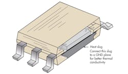
Next, use the right footprint for your component. The Fairchild Semiconductor ML6554 buck regulator comes in a 16PSOP package that can be mistaken for a SOIC-16, but it does have a thermal pad underneath that has to be there for the component to release the heat to the PCB (Fig. 1). This is how the component can handle the thermal requirements. If the thermal pad is not placed, the component will experience early shutdown due to thermal issues. Also notice that based on the ounces of copper on the layer (0.5, 1, 2, etc.), the heatsinking capability of the plane will differ, and wider area is required for thinner layers to achieve the same cooling effect.
Further consideration should be given to the component’s operating temperature range. Electrolytic capacitors are limited in the low temperature range, and capacitance varies significantly in the extreme temperatures.
Component Quality
The quality of the components plays a significant role in the switching regulator performance. Other parameters have to be right in addition to the values. For example, inductors of the same inductance value might have different saturation. Inductor saturation is when the magnetic characteristic of the device is stressed in excess of its ability and the device doesn’t behave as the inductor required.
Capacitors also vary their capacitance value as a function of temperature and frequency, so the correct type and quality are crucial for the correct operation. Similar capacitor values even from the same maker might have different features and prices. United Chemi-Con has a variety of electrolytic capacitors. Some are general purpose like the KMG series. Others such as the MZA series are low impedance. The MVH series offers higher ripple current. Other vendors offer a similar variety. Consequently, the capacitor value and type are not enough.
The source impedance is extremely important. Some inductance at the input of a switching regulator can help to decouple the current spikes from the switching power supply to the source. But in some cases, it can cause some ringing and spiking on the input voltage. Every dc-dc converter chip is designed to work with a specific combination of components with a range of acceptable values from a minimum to a maximum, so the datasheet must be scrutinized to validate any potential limitations. It is always good to perform all the calculations in spreadsheets and have a range (minimum and maximum) for all the component values.
On the other hand, a poor selection of components might jeopardize the product certification. Switching power supplies tend to be very noisy, to a point where electromagnetic interference (EMI) might be a concern. Using shielded inductors and high-quality capacitors might minimize the amount of noise present in the system. The capacitor’s equivalent series resistance (ESR) plays a role in the circuit stability and performance. Some configurations might call for a specific ESR, so you don’t always want low ESR. Pay particular attention to the input and output capacitance.
The input capacitors reduce the ripple voltage amplitude seen at the input of the converter to reduce the RMS ripple current to a level that bulk capacitors can handle. Ceramic capacitors have the extremely low ESR needed to reduce the ripple voltage amplitude. Therefore, it is important to place them close to the switching converter input. As the converter switches, it has to draw current pulses from the input source. An additional electrolytic or tantalum capacitor will help to provide enough energy to the load.
The output capacitor filters and minimizes any ripple at the output. This is a function of the capacitor’s ESR, which also can affect the regulator loop stability. Good quality capacitors will have a specified ESR. General-purpose electrolytic capacitors only specify ESR at 120 Hz, but high-frequency capacitors will have the ESR guaranteed at a higher frequency like 20 kHz to 100 kHz. The ESR will increase at low operating temperatures, and the output ripple voltage will increase accordingly. The ESR of a typical aluminum electrolytic may increase as much as 40 times at –40°C, so evaluate the use of electrolytic in low-temperature applications thoroughly.
The ripple current that the output capacitor can handle also should be considered. This current increases the internal temperature inside the capacitor due to power losses, so neglecting to verify the capacitor’s ripple current might have pyrotechnic consequences. Capacitors in parallel may be used to meet the ESR and RMS current handling requirements.
Some power supplies might require component certifications. Make sure you know what part needs to be tested and how it will be tested so your design is consistent with your targeted standard. If optocouplers are used for isolated converters, their design should consider light degradation over time, temperature limits, and common-mode potentials.
Worst-Case Scenario
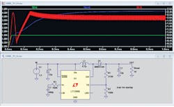
Running a simulation to verify that the design can handle the output current at the output voltage required in the time needed is always prudent (Fig. 2). It is important to know how the component’s variations perform over frequency, load, and temperature variations. Because of the dynamic nature of some switching regulators, their worst condition might not be in an extreme load, but rather somewhere in between. Testing your power supply for all the possible variations in your target circuit is important.
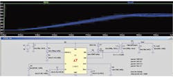
Prior to any implementation, simulate the correct operation over the entire operating temperature range. Simulations with Spice allow us to run Monte Carlo analysis or worst-case analysis to determine performance under different component tolerance variations (Fig. 3). It can also be used to vary the load condition. Linear Technologies’ LTSpice is a free version that works wonders. Texas Instruments (TI) offers TINA. And, other vendors have a variety of tools to simplify simulation, selection, and component evaluation.
Designers can also use the Texas Instruments WEBENCH tool to select and size dc-dc components and configurations (Fig. 4). Users can enter all the design requirements such as voltage input range, voltage out, and current out and temperature, and the software will select all the components and show the circuit configuration. In most cases, it will offer a range of options such as footprint, number of components, and cost.
For each design, the software will show thermal analysis and efficiency plots. Users can run multiple temperature scenarios, which the WEBENCH software currently cannot run simultaneously. For example, for Vin_min = 8 V, Vin_max = 48 V, Vout= 5 V, and Iout = 7.5 A, the LM5116 shows different data at different operating temperatures (see the table).
So, don’t take the first result for granted! Also, review all your circuit conditions from minimum temperature to high temperature. Before settling on a configuration, make sure it is the most adequate for the target application and environment. WEBENCH will always start with an easy temperature of 30°C as well. And, WEBENCH doesn’t cover all the TI switching regulators, so review the component selection on the TI Web site and validate them individually.
Many other vendors offer great lines of switching regulators, ultra-high efficiency, very low leakage, wider input range, low noise, multiple outputs, and even a combined linear regulation with the switching regulation. It is then prudent to review all of the potential candidates for suitability, cost, and performance.
As with any component, switching power components have a derating factor over their temperature range. Use the worse condition to estimate the power output your device requires. Characterizing the power components in the frequency range can provide some answers about the EMI performance.
Run your simulations with the worst-case scenarios and validate the components’ tolerances to make sure they will perform well in the temperature and tolerance range with a range of load variations. Simulation with different components might provide a broad range of alternatives, offer a better perspective for cost decisions, and open the opportunity to verify the component sizing.
PCB Area, Layout, And Footprint
Some components can be heatsinks for the PCB. The area used for these components plays a role in the heat released. Also, consider the thickness of the copper layer and if there should be any additional thermal vias and distribution. Make sure your manufacturing house can handle thermal vias in its production line if you are using them. Some libraries don’t include the right footprint to handle more power, and they might require additional copper definitions in the PCB layout.
Use short and wide PCB tracks to decrease voltage drops and minimize inductance. The high-frequency switching makes good component layout imperative. Place the switching elements first and close to the energy-storing element. Minimize the input and output loops to reduce radiation and high-frequency resonance problems. This strategy will minimize the current loops on the PCB that are the main culprit in electromagnetic radiation. Furthermore, look at the evaluation board and reference design to place the components. A solid ground plane and ground pour will help to spread the heat and enhance power transfer.
Performance Testing
Following the design guidelines and formulas for component selection somewhat validates the design. The circuit simulation might answer a few other questions in terms of operations in borderline conditions. However, the important aspect is the implementation for final performance testing. The final power and EMI verification is possible only on a real board with your targeted application.
The Federal Communications Commission mandates testing in the United States. Since all switching power supplies emit some level of EMI, they are potential culprits for failure. Careful component placement, layout, product integration, and packaging might mitigate overall emissions, but that needs to be validated in the final product.
Some new switching regulators allow the switching frequency to be changed, which should be explored in the case of EMI violations. Some dc-dc regulators offer dithering, which constantly varies the switching frequency on the fly. Therefore, the energy is spread out over a wider range and the resulting magnitude of the emitted energy at each individual frequency is lower.
Some cases might require an additional snubber on the switching element to mitigate the noise at the expense of some additional power. Finally, the full temperature range testing and field operation should be performed to confirm the adequate performance of the switching power supply and the rest of the electronics associated with the product.
Read more articles in TechXchange: Power Supply Design
References
Brian Erisman and Richard Redl, “Modify your switching-supply architecture for improved transient response,” www.edn.com/file/24543-46325.pdf
Jim Williams, “Switching Regulators for Poets. A Gentle Guide for the Trepidatious,”
http://cds.linear.com/docs/en/application-note/an25fa.pdf
Fairchild ML6554 datasheet, http://media.digikey.com/pdf/Data%20Sheets/Fairchild%20PDFs/ML6554.pdf
This file type includes high resolution graphics and schematics when applicable.
About the Author

David Bonyuet
Contributing Editor
David Bonyuet has been a passionate electronic gadgeteer and white hat hacker for more than 30 years. He graduated with a BSc in electronic engineering, obtained a PhD in telecommunication engineering from the Technical University of Catalonia (UPC, currently referred to as BarcelonaTech), and did the Entrepreneurship Development Program from the Massachusetts Institute of Technology (MIT). He has developed products for industrial, aerospace, medical, and robotic applications. He always strived for robust systems for the most stringent regulatory standards.
