A Better Way to Build Current Limiters and Circuit Breakers

Download this article in PDF format.
It’s now common to see circuit boards that carry hundreds of amps, especially in intensive data-processing applications, electric vehicles, and ac distribution. Despite their designed current-handling capacity, such circuits still need current limiters and circuit breakers to protect them from fault conditions. Appropriate current limiters and circuit breakers need to drop as little voltage as possible under normal operating conditions, be robust over the long term, and yet operate immediately and effectively in response to undefined fault conditions.
Limiting Current
Traditional current limiters include resistors, low-current positive temperature coefficient thermistors, and active circuits that give minimum losses and maximum control at higher currents. Active circuits are often built with bipolar junction transistors (BJTs) or MOSFETs. At lower currents, MOSFETs exhibit a low drain-source resistance (RDS(on)) and thus offer near zero loss—at a cost. At higher currents, the constant saturation voltage between a BJT’s collector and emitter (VCE(SAT)) may mean lower losses than incurred through the resistive drop of a MOSFET.
MOSFETs also work well in parallel. Two parallel BJTs sharing a fixed current “i” will each have half the power loss of a single device (VCE(SAT) × i/2). On the other hand, two parallel MOSFETs sharing current will each have one quarter of the dissipation of a single device ((i/2)2 × RDS(on)). The temperature rise in each MOSFET will also be much less than with a single device, and the positive temperature coefficient of RDS(on) will further reduce dissipation.
MOSFETs do have drawbacks. The fact that a current is being limited by dropping a voltage, and in turn causing constant power dissipation, means that it’s important to understand the forward safe operating area (FSOA) of the device and how this varies with temperature and bias conditions.
It’s also possible that an effect known as “current crowding” will produce hot spots that lead to failures, even if the device is apparently within its FSOA. Current crowding happens because the gate threshold voltage (VGTH) decreases with temperature and allows more current to flow at higher temperatures. Thermal runaway can follow if this effect exceeds the current limiting caused by the positive temperature coefficient of the device’s channel resistance. In addition, there’s local temperature variation due to die attach or wire connection reasons.
Figure 1 shows that, under certain conditions, one area of a die could be nearly 100°C hotter than the rest of it.
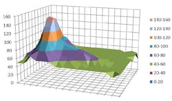
1. A hot spot on a 5- × 5-mm power MOS transistor.
The Advantages of Normally-on SiC JFETs
Wide-bandgap semiconductors have some appealing characteristics for current limiters. A JFET is normally-on with VGS = 0 V, and it has a very flat channel-saturation-current curve when measured against drain-source voltage (Fig. 2).
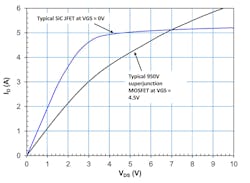
2. Comparing SiC JFET and Si-MOSFET saturation current characteristics.
The initial slope of both curves in Figure 2 follows the RDS(on) of the device, but above a certain VDS, the SiC JFET limits current well, while the current in a similarly rated Si-MOSFET continues to rise, reaching the dissipation limits set by its package much sooner. It’s also the case that the electron mobility in a SiC device falls with temperature, which also helps to reduce saturation current.
SiC JFETs are also better than Si- or SiC-MOSFETs when operating in their “linear” regions. At gate-source voltages around the device’s threshold, the temperature coefficient of the transconductance of SiC is negative, compared with positive values for the other technologies. This provides some self-limiting, with less drain current available at high temperatures for a given gate-source voltage. In addition, the mechanism prevents the previously mentioned runaway effects in Si-MOSFETs. When saturation-limited, SiC JFETs can also be paralleled, in the knowledge that the channel temperature coefficient will force current sharing.
A simple bidirectional limiter (Fig. 3) can be built just by choosing a SiC JFET that achieves the desired limit current. If designers want greater control over the current limit, they can add a ballast resistor to act as an end-stop to the current, at the expense of some continuous dissipation in normal operation. An alternative approach is to use an active circuit that senses current and closes a control loop to the SiC JFET gate. SiC JFETs are also robust, sustaining peak junction temperatures greater than 600°C without failure.
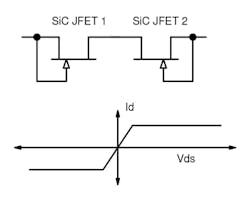
3. Shown is a simple bidirectional current limiter.
Figure 4 compares SiC JFETs with other technologies, using the channel resistance per unit of chip area as the figure of merit. It shows that using SiC JFETs means smaller devices and more die per wafer for equivalent performance.
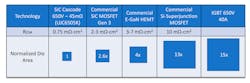
4. Device types are compared on the basis of channel resistance per unit die area.
SiC JFETs in Your System
Current limiters are often used to protect against lightning strikes, or the extreme transients seen in rail applications. In these applications, a current limiter may have to dissipate kilowatts for short periods. As previously discussed, SiC devices offer good robustness and high temperature operation. Some limiters follow the SiC JFET with transient suppressor diodes, which can offer high avalanche voltage ratings, robustness, and high-temperature operation if they’re built with SiC technology.
Breakers, Not Limiters
In high-power systems, current flow must be stopped, rather than limited, to protect circuitry effectively. Mechanical circuit breakers offer low losses and perfect isolation, but they can be slow to operate, and their contacts can arc and wear out over time.
IGBTs, gate turn-off thyristors (GTOs), and more recently MOSFETs have all been explored as the basis for solid-state circuit breakers, but the circuits they’re used in often need extra power rails or internal power converters to bias the active devices. SiC JFETs don’t—they can be configured to act as a true two-terminal device, handling all of the necessary current sensing and biasing internally.
Figure 5 shows how this might work. UnitedSiC has prototyped a version of this circuit rated at 100 A and 600 V that trips within 20 µs and has an insertion loss of just 0.91% in a 150-kW, six-phase inverter design.
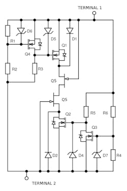
5. This is the two-terminal self-biasing circuit breaker concept.
Summary
While wide-bandgap devices are often recognized for their performance in high-speed switching, SiC JFETs are also useful for building simple, efficient current limiters and circuit breakers.
Dr. Anup Bhalla is VP of Engineering at UnitedSiC.

About the Author
Anup Bhalla
VP of Engineering
Dr. Anup Bhalla oversees all product development at UnitedSiC and became an investor in the company when he joined in 2012. Prior to joining UnitedSiC, Anup held various product development and marketing positions at Alpha and Omega Semiconductor, which he co-founded. He’s the author or co-author of nearly 100 patents through his career at Harris, Vishay Siliconix, AOS, and UnitedSiC. He received his Bachelor’s degree from the Indian Institute of Technology, Delhi, and his Ph.D from Rensselaer Polytechnic Institute, both in electrical engineering.
Comment About the Article
To join the conversation, and become an exclusive member of Electronic Design, create an account today!

Leaders relevant to this article: