Efficiently Reduce High Supply Voltages To Accurate Low Voltage

When a relatively high input of 24 V or more must be very accurately regulated down to a much lower voltage, such as 3.3 V or less, with very low quiescent current, there's no off-the-shelf solution available. For example, if one needs to efficiently run a low-power microcontroller from a 24- or 48-V battery supply, it typically takes two cascaded regulators. And, the quiescent current is likely to be more than the load current.
The simple, low-cost circuit shown in the figure will do the job on a mere 75 µA. Moreover, the input voltage is limited only by the rating of the series-pass MOSFET. For best accuracy (0.1%) and lowest current (65 µA), an LM4041A or LM4051A micropower precision shunt reference is used for U1. For less critical applications, the lower-cost LMV431B will regulate at 0.5% on 80 µA. Less accurate grades are also available at lower cost.
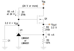
This circuit produces highly regulated low voltages from inputs of 24 V or more while drawing under 75 µ A of quiescent current.
Operation is straightforward. When VIN is applied, R1 pulls up Q1's gate, turning it on. As VOUT rises, a portion is fed back to U1, causing it to pull the gate down. U1 will then hold the gate of Q1 at whatever voltage is necessary to keep VOUT at the desired set point. Therefore, the junction of R2 and R3 will be held equal to U1's reference voltage. C1 slows down Q1's turn-on to prevent overshoot and should be at least 10 times the FET's drain-to-gate capacitance. It can be made much larger if a slower turn-on is desired, though.
R1 is sized so that the lowest input voltage will supply the minimum current required by U1 to regulate. If the input voltage will vary over a very wide range, R1 can be replaced by a simple two-transistor current source to keep the quiescent current low, regardless of the input.
The output voltage equals 1 + (R2/R3) times the reference voltage of 1.212 V. Because the reference current is in the nanoamps, we can set the R2-R3 divider current at 10 µA and ignore it. The values shown should give an output of 3.315 V.
Q1 is selected based on the maximum input voltage, output current, and power dissipation. For just a few milliamps of output current, an SOT-23 device will suffice, while a larger package can supply several amps with no other circuit change. If desired, one could add a resistor in the FET's drain circuit to reduce its dissipation. This would also limit current in the event of a shorted output.
If an LM4041- or LM4051-type device is used, its cathode should not exceed 10 V. Thus, a logic-level or low-threshold FET should be used to ensure that the gate will only be a few volts higher than the output. If the FET's gate must be higher than 10 V, one or more diodes or a zener can be placed between U1 and the gate without degrading the accuracy. A zener could also be added across U1 for protection in case the output gets shorted to ground. For higher output voltages, the LMV431 should be used, because its cathode can withstand 35 V. For lower voltages at even lower current operation, the LM185/285/385 only requires 10 µA, but its cathode can't exceed 5.3 V.
About the Author
Comment About the Article
To join the conversation, and become an exclusive member of Electronic Design, create an account today!

Leaders relevant to this article: