This file type includes high-resolution graphics and schematics when applicable.
If you’re bringing ac power directly into your new product, then the implementation methods to get a safe device need to be carefully considered as part of the design. If you don’t, getting things wrong with ac power can lead to deadly devices, and smoke-filled outcomes.
The multitude of devices now using low-voltage dc power provided from an external ac-dc converter allows many EEs to remain blissfully unaware of high-power safety considerations. Using external ac adapters allows designers to largely ignore many high-voltage product-safety requirements. Designing with power inlets under 25 V, where the “Extra Low Voltage” (ELV) concept is applicable, simplifies things a lot, putting safety issues largely in the hands of the designer of that ac adapter.
Product safety has many different aspects. For this article, we look at getting electrical mains power into a device safely and properly configuring the system power supply. Functional safety is the start, but when something breaks, power systems also require a safe failure method. As with many of the articles I write, this one was motivated by dealing with a number of design engineers who have never dealt with ac power directly, or the issues associated with a system power supply that both functions and, equally important, fails safely.
Many older (especially prior to 1960) electrical products were inherently unsafe or could become deadly with a single fault failure. Metal enclosures (prior to the widespread use of plastics) and a lack of a ground safety made for a deadly combination. Thankfully, consumer electronic products have a fairly short life, so many of those devices are now obsolete. However, buildings last longer than electrical appliances, and older construction projects still have a wealth of unsafe insulation on wires, systems that lack proper grounding, and circuit installations that are unsafe or need updating.
An aside: Medical devices have a special regulatory maze to navigate. If you’re designing a medical device, read “Know Your Regulation Before You Design Medical Electronics” to avoid redesign. Safety requirements have a strong influence on medical electronics design. Consequently, you need to understand the regulations early in the design cycle.
Most EEs deal with ELV devices that are subdivided into “Separated ELV” (no ground return path used) and “Protected ELV” (a ground earth safety is present). Recently, IEC 62368-1 (Safety Requirements for Audio/Video, Information & Communication Technology Equipment) has become the standard for ELV safety, and has more carefully defined ELV devices as the “ES-1 region” that limits both current and voltage. For ELV devices, safety requirements are very minimal, with some form of overcurrent protection and a non-conductive enclosure generally being sufficient.
AC Power and Grounding Safety
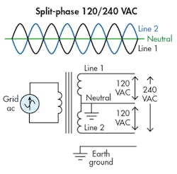
A refresher: What comprises ac mains power (see figure, below right)? It’s surprising how many EEs aren’t aware of what typical ac power looks like. (Utility power is no longer taught in ECE curriculum?)
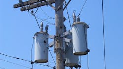
In the U.S., at the residential level, the grid feeds a distribution transformer providing a “split-phase 120/240 system” output. What reaches a typical wall outlet (120 VAC in the U.S.) is a three-wire system of Line (aka Hot), Neutral, and Earth Ground. Normally, current passes through Line and Neutral with zero current in the Ground. Under normal operation, Neutral and Ground should be at roughly the same voltage.
This 120 VAC isn’t a symmetric differential signal; only the Line signal has a sinusoid. However, when both ends of the utility stepdown transformer secondary are used (220 VAC in the U.S.), the output voltage is a symmetric differential signal centered around the Neutral signal. (Neutral is the center tap from the distribution transformer.)
Devices with an ac mains input exclusively use the Ground connection as a conductive enclosure connection to guarantee that the outside of the device remains at ground potential. Neutral and Ground are only connected together back at the distribution point. Prior to 1960, electrical residential wiring was only two wires, without the ground safety connection, which could produce unsafe devices in many failure scenarios.
The “Single Fault Safe” concept is simple: Any element of the system can fail in an open-circuit state, closed-circuit state, or contact any other element in the system and not cause danger to the user. Introduction of a ground safety return path into modern power wiring allowed for a safe system in most single-fault situations, where the grounded enclosure, in conjunction with a fused “Line” connection, could keep a device safe.
IEC 61140: “Protection Against Electric Shock” can provide detailed information on the regulatory restrictions and classification of power safety. In brief, devices that use a metal chassis and enclosure structure that’s attached to a ground safety connection are defined as Class I devices. Their failure safety depends on the presence of a properly connected external ground path.
Some devices have only a Line and Neutral connection, and meet safety requirements through the use of a “Double Insulated” structure. For these devices, the internal wiring and active circuits are encased in a secondary insulating enclosure. In this manner, the device is allowed a single-fault failure without allowing the user to be exposed to a high-voltage contact. Some older power tools used metal enclosures and had no ground wire. These could become deadly if an internal wire insulation failed, making the enclosure live and, in turn, a user potentially becoming the return path for current.
Double-insulated devices are considered Class II devices; the safety redundancy of the structure doesn’t depend on the external ground return path. Consequently, double-insulated devices have been very popular in electric power tools—they remain safe when connected to electrical power with questionable ground paths, as frequently happens in construction environments.
Overcurrent Protection and the Weakest Link
Overcurrent protection is one of the most basic things to protect a system. What are the options here? In an overcurrent situation, things can turn off in four main ways: fuses, circuit breakers, PTC devices, and electronic sense-shutdown.
Fuses are commonly used for their simplicity and low cost. However, fuses are slow, they require manual replacement to restart the system, and they aren’t terribly accurate. In some situations, you would like to control both current and time needed for the fuse to do its job. However, overcurrent level and activation time are interactive, so don’t expect fast and accurate here. Nonetheless, the fuse is a low-cost, simple, and reliable device, and is still the go-to solution in many cases.
The basic circuit breaker suffers many of the limitations of fuses, with speed and accuracy “good enough” for most situations. To gain the convenience of a resettable device, a penalty is paid in cost. A similarly rated circuit breaker to a fuse can be considerably more expensive to implement. Also, circuit-breaker reliability can suffer from internal corrosion issues due to hostile environments if the devices aren’t hermetically sealed.
The polymeric positive temperature coefficient device (widely known as a PTC) can be considered a self-resetting fuse. They warm up, due to too much current, and the device goes into a high-resistance mode, limiting the current until the device cools off and returns to a low-resistance state. The devices do have some less-than-ideal internal on/off resistance, but the PTC serves well for situations where auto-reset is desirable. Generally, the devices can be embedded in the PCB design for a low-cost design solution. The PTC also has limitations of accuracy and response time, as is the case with all thermally triggered devices.
Using active electronic circuits for overcurrent detection and shutdown comes in many variants. The basic concept is a set of detection circuits for current and/or voltage to determine if the applied power is outside specified limits, which triggers suitable circuit controls to shut down or limit performance. These systems can be very fast if needed, and also very accurate if the system requires such features. The price paid here is complexity and cost. Frequently, this approach is unneeded and one of the simpler methods is suitable.
Whatever current-shutdown method is employed, the system being defined needs to make sure that the “weakest link” is the actual current-shutdown device. Most of us have seen devices where something else burned up while the fuse or circuit breaker survived without doing its job. With devices limited by their thermal characteristics (resisitors, transformers, PCB copper connections, etc.), this is straightforward. However, power-switching semiconductors need special attention due to their ability to self-destruct more quickly than a sluggish fuse or circuit breaker. Many switching power supplies have electronic overcurrent monitoring built into their design for this very reason.
Whatever method you use for protection of overcurrent situations, setting the parameters for the trip point needs to consider both min-max sustained and startup surge currents. Also, your system may have high- and low-current sections where a failure in the low-current section requires a lower-value current shutdown to protect that part of the system. A common design mistake is using single overcurrent shutdown in a situation where the low-power system self-destructs, since it’s tied in parallel with the high-current system.
Other Useful Techniques
Having the power system fail safely requires looking at certain key parts that do commonly fail and determining what happens due to the failure. The most common failures tend to occur in the dc power supply, namely the electrolytic capacitors and the power-switching transistors. What fails after the electrolytic capacitor shorts or opens? Ideally, you want your current-overload device to open up next, but in many improperly designed devices, a smoke show is the outcome. In a similar manner, the failure of the power-switching transistors needs to be examined, too.
PCB layout techniques must change for high-current/voltage situations as well. Copper weight and resistive losses in interconnects are one important consideration. In addition, physical trace separation requirements change for high-voltage systems, with IPC-2221B (Generic Standard on Printed Board Design) providing size and separation guidelines.
Thermal monitoring of performance-critical devices can be useful, with protection control built into the system. For some devices this provides another layer of safety and capability to stress devices to their thermal limits without crossing the line of destruction. Older devices used thermocouples, but silicon-based thermal monitors with digital interfaces to a local controller are a more modern approach.
High-performance microprocessors include thermal monitors on the semiconductor substrate, which are digitally linked to cooling systems and clocking-rate controls. The processor warms up, and the fan gets turned on to an appropriate speed, or the clocking rate is slowed down. This is common for modern PCs, while older devices ran with full-on fans for all thermal situations.
Conclusions
The ac mains power into a system requires a strategy to avoid electric shock and ensure product safety. Designs also need to define safety in terms of how a system fails yet remains safe. Overcurrent protection is part of the safety strategy, and needs to be implemented as part of an intentionally weakest-link scenario.
Many first-generation devices don’t include these considerations in their design, and consequently need to be revised to get UL, CE, or other safety certification. If you include ac power internal to your design, grounding or insulation safety methods need to be part of the system in order to function and fail safely.
About the Author

Jerry Twomey
Founder and Engineering Consultant, Effective Electrons
Jerry Twomey has extensive experience designing electronics for medical devices, electromechanical systems, and transistor-level integrated circuits. This includes many consumer, medical, aerospace, and commercial products.
Jerry holds several patents and is an author of multiple trade magazine publications, many of which appeared in Electronic Design magazine, providing solutions for commonly encountered design problems. He teaches seminars in embedded systems, IC design, EMC, and medical technology, and has lectured at UCSD. Jerry has also chaired the San Diego IEEE chapters for Microwaves and for Solid State Circuits.
Jerry Twomey is the author of Applied Embedded Electronics – Design Essentials for Robust Systems, a comprehensive reference book covering the design process for embedded-systems electronics from initial concept to final PCB.


