This file type includes high resolution graphics and schematics when applicable.
Now utilities are turning their attention beyond electricity to another energy resource: gas. If it makes sense to switch electricity metering to a more accurate, more flexible smart meter, then the same can be done for gas metering. This has led to a new generation of emerging gas-metering techniques.
Gas Metering is not Electricity Metering
It’s important to note at the outset that gas production, delivery, and metering differ from electricity generation, delivery, and metering. Several factors distinguish one from the other:
First, electricity must be generated as it’s used; there’s currently no economically viable way to store generated electricity for later use. Gas, however, is easily stored and delivered for future use as needed. Gas utilities have no concept of “peak use” or “off-peak use,” factors that electric utilities must consider when planning generation and transmission capacity.
Second is consumption. The challenges associated with accurate metering of electricity and gas consumption differ significantly. Once you measure the instantaneous values of voltage and current in an electricity meter, it’s a simple matter to compute the instantaneous power, and by integration, the energy consumption.
Gas, on the other hand, is a compressible fluid—the energy content of a cubic foot of a fuel gas depends on its pressure and temperature. Consider a cubic foot of fuel gas at two atmospheres pressure and a given temperature. It will comprise a greater mass of gas (and, thus, deliver more energy) than the same volume of fuel gas at the same temperature, but at one atmosphere pressure. A cubic foot of fuel gas at one atmosphere and 0°C will comprise a greater mass of gas (and, thus, deliver more energy) than the same volume of fuel gas at the same pressure, but at +60°C.
Finally, there’s the energy actually delivered. Electricity is, well, electricity. With a few notable exceptions, a 120-V, 60-Hz single-phase circuit in one locale will deliver the same power as a 120-V, 60-Hz single-phase circuit in any other location. But the chemical makeup of natural gas can vary significantly from one location to another.
Generally pulled from the ground and delivered for use, gas consists of mostly methane with impurities in the form of other gases. Burning one kilogram of pure methane will release about 55.5 MJ of energy. However, if the gas contains other combustible compounds (e.g., ethane, propane, or butane), it increases the energy density. That’s because higher-order carbon compounds release more chemical energy when burned than lower-order compounds. But if the fuel gas contains inert gases (e.g., carbon dioxide or nitrogen), the energy density—the heat delivered by burning the gas—is reduced.
Utilities constantly monitor the quality of the gas in distribution to determine the exact chemical makeup of the mixture. In fact, to account for the varying heat content of the product, some utilities apply a “therm factor” to the consumed volume of gas.
Limitations of Gas Metering Today
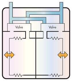
Most currently deployed gas meters are diaphragm or bellows types of positive-displacement meters (Fig. 1). The flow of gas through the meter drives the meter mechanism. Each time the bellows expands and contracts, a set amount of gas is transferred to the output port. The motion of the bellows drives a mechanical linkage that opens and closes a set of valves, directing the flow of gas to the appropriate chamber. The same mechanism that drives the valves also drives a mechanical counter, so that the exact number of cycles (and, by inference, the exact volume of gas) is always known.
Bellows-type meters have been available for more than a century and have a service lifetime measured in decades. But they have limitations. Purely mechanical, they cannot communicate. They cannot provide their measurements for remote reading without a significant investment in external hardware. They’re difficult to compensate for temperature. And, as with all mechanical devices, they’re subject to wear.
Emergence of Electronic Gas Meters
While several existing alternative technologies could replace bellows-type meters, two electronic designs combine the requisite accuracy, economy, and long-term stability needed for a practical deployment in revenue meter applications. The first meter type employs a heated element and a mechanism to measure heat convection in a moving medium. The second type uses the characteristics of sound propagation in a moving medium.
Both of these technologies are sampling methods, not positive-displacement methods. They periodically measure the flow velocity of the medium, and from that infer the volume or mass flow rate of the medium. Meters of this type must assume that the flow rate is constant between samples—a reasonable assumption if the sample rate is high enough. But higher sample rates raise another issue: battery life.
Bellows-type meters operate directly from the motion of the gas being measured. Electronic meters, however, require a source of electrical energy to operate, which is provided by a battery. Every sample taken by the meter absorbs a small amount of energy from the battery. The more frequently the gas velocity is measured, the more rapidly the battery will drain.
Measuring flow with a temperature sensor requires a source of heat and a way to determine how the heat flows in the moving medium. Two types of temperature-based sensors are commonly used today: a self-heated thermistor-based sensor, and a separately-heated, thermopile-based sensor.
Thermistor Designs—Measuring Gas Flow by Heat Flow
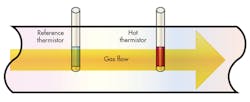
The thermistor-based flow meter uses a pair of calibrated positive temperature-coefficient (PTC) thermistors. A thermistor indicates a change in temperature via a change in its electrical resistance (Fig. 2). In a PTC thermistor, the resistance increases with increasing temperature. Drive enough current through the thermistor and it will begin to self-heat, raising the resistance and limiting the current.
To measure flow rate, two thermistors are mounted in the flowing medium. One thermistor measures the temperature of the medium; the other is driven with enough electrical current to raise its temperature to some fixed level above the temperature of the medium. In still gas, the hot thermistor will lose heat through both radiation and convection (i.e., heating the air around the thermistor). The electrical energy that heats the thermistor is exactly balanced by the loss of heat by radiation and convection. As a result, the thermistor’s temperature is stable.
When the gas is flowing, the convection component of heat dissipation from the thermistor increases and the thermistor cools. The driver circuit senses the change in the current (i.e., as the hot thermistor cools, it exhibits less resistance to the flow of current), and raises the voltage across the thermistor to maintain a fixed temperature difference between the reference thermistor and the sensing thermistor. The voltage required to keep the thermistor at a fixed temperature above the reference thermistor is a monotonic function of temperature. Consequently, the system can compute the flow rate knowing only the temperature of the gas and the voltage applied to the hot thermistor.
That type of measurement system is robust and accurate, but it’s not the best solution for utility meters because the sensing thermistor has to be kept hot. This would quickly drain a battery. Nonetheless, such a system points the way toward more energy-efficient temperature-based flow meters.
More Energy-Efficient Thermoelectric Sensor Designs
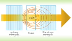
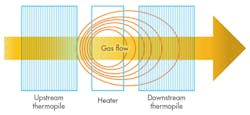
This brings us to the separately heated thermopile-based sensor (Fig. 3). The heater and two thermopile sensors are fabricated on a single piece of silicon using microelectromechanical-systems (MEMS) techniques. In these systems, a tiny element heats the gas in the vicinity of two or more temperature sensors. In still gas, the sensors report the same temperature. But if the gas is moving, the sensor downstream from the heater reports a higher temperature than the sensor that’s upstream. This is because the flow of the medium moves warmer, heated gas toward the downstream sensor and away from the upstream sensor.
At first consideration, one might think that this system suffers from the same poor battery performance observed in the thermistor-based meter. But this isn’t the case at all. Because the MEMS geometry is so small, the heating element can turn on nearly instantly to warm the gas. For this reason, it doesn’t have to operate continuously—the heater cycles on and off when needed for sample measurement.
Ultrasonic Flow Metering Emerges
Another, new option for gas-flow meters has emerged that’s based on ultrasonic principles (Fig. 4). In this configuration, a pair of transducers is placed in the gas flow. To take a measurement, a pulse launches from the upstream transducer toward the downstream transducer, and the time of flight (TOF) of the pulse is computed. Then, a pulse launches from the downstream transducer back toward the upstream transducer, and the TOF of this pulse is computed. The difference in the flight time between the pulse traveling with the flow of gas and the pulse traveling against the flow of gas determines the velocity of the gas flow.
The ultrasonic flow meter doesn’t sample the flow at a single point as with thermoelectric designs. Instead, it sends the pressure wave down the bulk of the material, providing a more accurate indication of the flow rate. While most designs will mount the transducers inside the spool body, the transducers for this meter can be mounted to the exterior of the spool body if so desired. In this configuration, there’s nothing inside the pipe to impede the flow of gas.
Pros and Cons of Temperature-Based Designs
The MEMS thermoelectric flow sensor and the ultrasonic flow sensor are the most frequently mentioned alternatives for residential gas metering. How do these sensors stack up against traditional bellows-type meters and against each other?
Electronic Output Enables Communication Options
In the always-connected world, the manner in which a meter integrates with an existing network is always a consideration before deployment. In this contest, the sampling meters are clear winners over bellows types. In both the ultrasonic flow measurement and the MEMS-based thermoelectric flow measurement techniques, the output is electronic and not mechanical, lending itself to direct connection to communication facilities.
However, a notable difference exists between the two competing temperature-sensing technologies—the form of output. The thermoelectric design is natively analog, because the output signal is derived by taking the difference between the outputs of the two thermopiles. The difference signal can then be applied to an appropriate analog-to-digital converter (ADC), scaled, and linearized to provide the desired flow values.
The ultrasonic flow sensor’s output, in contrast, is inherently digital. Flow rate is computed by counting the TOF in both the upstream and downstream directions, and then processing the two values in the digital domain. This doesn’t necessarily mean that the ultrasonic technique is qualitatively better or more accurate. Nonetheless, removing the ADC step eliminates one potential source of inaccuracy from the signal chain.
Packaging Dictates Design Flexibility
There’s a striking difference between the packaging for ultrasonic TOF sensors and MEMS-based thermoelectric sensors. MEMS-based sensors are tiny, measuring a few millimeters on a side. They’re fabricated using techniques similar to those used for silicon chips, resulting in nearly microscopic structures.
From a practical standpoint, this means that a MEMS-based sensor can’t be placed by itself within the bulk flow of gas. Any solid material flowing along with the gas (e.g., dust and other particulates) that accumulates on the tiny structures of the heater or temperature sensors would adversely affect accuracy. In fact, most practical MEMS sensors take positive steps to segregate dust from the gas flow over the sensor. For this reason, the sensor itself is always sealed within a package that serves as a gas sampling chamber. Electrical connections to the package provide power and deliver the flow measurement, whether analog or digital, to subsequent circuitry for processing.
The ultrasonic TOF sensor, however, simply drives acoustic transducers. These transducers can be placed anywhere within the flow of the gas or, indeed, on the outside of the pipe, if desired. Now it’s the system designer who configures the processing firmware on the host microcontroller to convert the TOF measurements to flow units for the particular configuration of spool body, transducers, and geometry.
In this contest, the ultrasonic TOF sensor is much more flexible because it allows the designer to employ a virtually unlimited set of design choices. When using a thermoelectric sensor, the sensing element’s form factor will dictate the choices.
Managing Power Consumption
In an electricity meter, the measurement mechanism draws a small amount of power directly from the circuit being measured. Similarly, a bellows-type positive-displacement meter derives its operating energy from the pressure differential between the input and output ports.
A sampling gas meter doesn’t have the luxury of using freely available power to drive its measurement logic. It generally derives its power from a battery. But a utility meter is expected to provide 10 to 20 years of service with minimal maintenance. That means that you must either design in a very large battery or really minimize power consumption.
For example, a lithium-thionyl battery of reasonable capacity (a C-size cell) delivers about 8.5 Ah of capacity at a terminal voltage of 3.6 V. For this battery to last 20 years, the meter can draw no more than about 50-µA average current. Is that a reasonable requirement?
Three factors should be considered when estimating power consumption of a sampling meter: the active current (i.e., the current drawn from the battery when the meter is actually making a measurement); the standby current (i.e., the current drawn from the battery when the meter is between measurements); and the sampling rate. Chips designed to drive acoustic transducers for TOF measurement and MEMS-based flow-measuring devices both have submicroampere standby current, and we can assume similar sampling rates. That leaves active current as the only differentiating factor.
MEMS-based thermoelectric flow sensors require about 1 mA when active, and must stay active for between 70 and 100 ms, depending on flow rate. The most frequently cited average current consumption is 70 µA, and that’s before we account for a supervisory microcontroller. Just this measurement consumes about 70 µA-seconds per sample.
Ultrasonic TOF flow sensors tend to be more conservative with power. The active current is greater (about 4.5 mA for the time measurement and about 2.5 mA for computation phase). But once the command is issued, it’s complete within a few milliseconds. Assuming a 5-ms cycle time and about 5-mA average current, the ultrasonic flow sensor draws a total of about 25 µA-seconds per sample.
Compensation and the Gas Laws
Utilities deliver gas priced to the end consumer at a certain value per 100 standard cubic feet (SCCF) of gas. One standard cubic foot is one cubic foot of gas at 60°F and at one atmosphere pressure. One cubic foot of gas at a different temperature or pressure will constitute a different mass of gas and, therefore, a different amount of fuel. For this reason, if the gas is delivered at a temperature or pressure other than 60°F and one atmosphere, compensation factors must be included to convert the measurement back to SCCF.
The objective is to bill for energy delivered, regardless of other factors. The amount of energy delivered depends on the mass of gas delivered and the composition of the gas. But most gas meters actually measure the volume of gas delivered, not the mass. The mass, volume, temperature, and pressure of any gas are all related by well-known gas laws: Boyle’s law relates pressure and volume at a fixed temperature; Charles’ law relates volume and temperature at a constant pressure; Gay-Lussac’s law relates pressure and temperature at a fixed volume; and Avogadro’s law states that the number of molecules of gas at a constant temperature and pressure are proportional to volume.
Consequently, it’s necessary to regulate the pressure going to the meter. If pressure were allowed to vary, it would be impossible to determine the mass of gas delivered from only the volume. Regardless of the input pressure to the regulator, the output pressure from the regulator to the gas meter is fixed to about 0.25 psig. Carefully regulating the pressure to the gas meter eliminates any variations of energy delivered due to pressure changes.
But what about temperature? This is where the thermoelectric flow sensor and TOF flow sensor differ once again.
The thermoelectric flow sensor is a mass flow sensor, not a volumetric meter (like a bellows-type meter) nor a velocity flow sensor (like an ultrasonic flow meter). It detects the amount of heat moved from the heater to the thermopile, and that heat will increase with both the rate of flow (velocity) and density of the gas. On the other hand, an ultrasonic flow meter measures only the velocity of the medium in which the sound wave is traveling, relative to the speed of sound in the gas.
For this reason, the thermoelectric flow meter is inherently temperature-compensated, since it measures the mass flow rather than the volume flow. The ultrasonic flow meter must measure the temperature of the gas and apply gas laws to convert from the actual cubic feet to standard cubic feet.
One more compensation factor must be considered: the makeup of the gas. So long as the gas being measured doesn’t differ too much from pure methane, the speed of sound (and, thus, the accuracy of the ultrasonic meter) will remain constant within a fraction of a percent. If the gas makeup changes, the energy content of the gas will change, but the utility will account for that with a monthly analysis of the delivered gas.
Because the thermoelectric flow sensor measures the mass flow, the thermoelectric flow sensor will report a greater flow with gas impurities than an ultrasonic sensor. Thus, the compensation factor will differ for the two types of sensors.
Summary
Gas meter designers looking for more economy, accuracy, and design flexibility have two good alternatives to traditional bellows-type meters: thermoelectric and ultrasonic flow-sensing technologies. The fastest and easiest designs can be executed with the thermoelectric sensors, since they come ready-to-use in their own spool body. However, the most accurate and lowest-power designs will be achieved with ultrasonic sensing technology.
About the Author
Ben Smith
Software Manager
Ben Smith joined the firmware engineering team at Maxim Integrated in 2003. Since then, Ben has designed hardware and software systems that made their way into the company’s products. Currently, Ben is engaged in product development for Maxim’s Smart Grid group. A holder of eight U.S. patents, he earned his BSEE from the Missouri University of Science and Technology.


