Integrated Stepper Motor Driver Solutions Require Thermal Design Calculations
One constant trend in the automotive world is the push to reduce the size of electronic components and electronic control units (ECUs). While this development has many benefits for car manufacturers and end customers, there are also challenges for the developers of these systems.
Especially for power drivers, robust application design requires an accurate estimation of the thermal power dissipation on a system level. There is a method to calculate the thermal power dissipation of a stepper motor driver, derived from a simple example to a model that includes the various configuration options and modes of a state-of-the-art stepper driver. These motor drivers feature:
- Current regulation based on pulse-width modulation (PWM)
- Integrated programmable waveform generation
- Configurable current decay modes
- Motor state and failure diagnosis
Conduction Losses
Every MOS transistor-based switch has a drain source resistance when switched on (RDS(on)). This will cause thermal power dissipation during the ON state:Switching Losses
There are intrinsic parasitic capacitors, and for every switch transition, there is a charging time or discharging time for these capacitors. Consequently, the power switch will need a finite time for the transition from a non-conductive state to a conductive state and vice versa. This is especially the case for driving methods based on PWM signals, as the switching losses may have a significant impact on the overall thermal power dissipation. Furthermore, the switch transition times are often prolonged by slew rate options to avoid fast rising and falling edges to improve electromagnetic compatibility (EMC) performance, often at the cost of higher thermal switching losses.
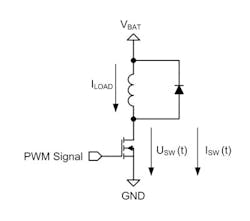
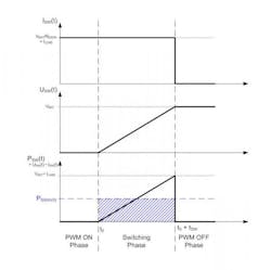
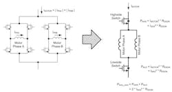
To simplify the calculation of the switching losses for an inductive load, it can be assumed that the voltage across the switch will change linearly and the current is constant. The simplifications in Figure 2 lead to a formula for calculating the average thermal power dissipation during a switching phase:
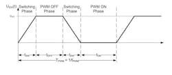
The switching losses considering the switching time and the PWM frequency can then be calculated using:
In summary, the thermal power dissipation is calculated by the average thermal power dissipation in a PWM period. This dissipation is calculated by differentiating the PWM period into switch states, calculating the power dissipation for each individual switch state, and then applying a weighting according to the switch state duration.
Challenges & Prerequisites
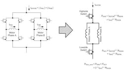
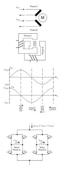
For a bipolar stepper motor driver, the calculation conditions seem to be rather complex. The motor consists of two phases that are driven with an H-bridge instead of a single MOS switch (Fig. 4a and Fig. 4c). The motor current is not constant and consists, in the case of a bipolar motor, of two sine-shaped currents in each motor phase that have a relative phase shift of 90° to each other (Fig. 4b).When the motor is stopped, the current will not be completely set to zero. Instead, it will be reduced. This is commonly called “hold current,” which is needed to provide a minimum force to maintain a rotor position. (Typically the lowest possible current for the application is being used here because due to the missing back electromotive force in standstill, the only active load is the ohmic resistance of the motor coil and the electrical energy is directly converted into thermal power losses in the motor.) The motor phase currents are permanently regulated using a PWM signal.
The switching states and the number of transitions in this current regulation loop depend on the selected current decay mode and may vary in one electrical revolution. This implies that the PWM switching states as well as the number of state transitions in one PWM cycle may vary, directly influencing the switching losses.
Many application-oriented configuration options are commonly used to optimize the system. But in return, they directly affect the thermal power dissipation like slew rates, cross-current protection delay, and filter times.
The procedure to create a thermal evaluation of a stepper motor driver system is very similar to the initial calculation example, considering certain requirements and prerequisites. First, an application load profile is required to consider the ratio in between nominal driving current and hold current. Generally:
can be used.
Pthdis_drive and Pthdis_hold represent the thermal power dissipation for one specific target current (nominal driving current and hold current). Both values include:
- Conduction losses (Pthdis_cond)
- Switching losses (Pthdis_sw)
- Cross conduction protection losses (Pthdis_cc)
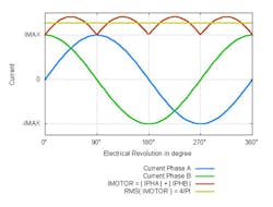
The simplified calculation above is only valid for the conduction loss calculation because the current is calculated with a power of 2, eliminating the term (sin²(t)+cos²(t)). For the other cases (switching loss and cross current protection loss), the motor current has to be calculated by:
For phase and motor currents, see Figure 6.
Thermal Power Dissipation Calculations
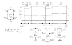
To calculate thermal power dissipation, the first step is to differentiate the switching states in one PWM period (Fig. 7). Therefore, an in depth look at the switching sequence is mandatory.A typical “slow decay” PWM period begins when the H-bridge has to be set to a defined state. Therefore, all switches are deactivated first. Before any switch can be activated again, a cross-current protection time has to be passed. Then the switches are activated again, and the PWM ON state is reached. This state persists until the current limit for this motor step is reached in the motor phase or a new PWM period starts. If the current limit has been reached, then there is another switch transition followed by a cross-current protection time. Then the switches are activated again to enter the PWM OFF state until a new PWM period starts. For the PWM OFF state, several user-configurable options are possible:
- Slow decay: Both high-side switches are active so the current in the motor phase has a freewheeling path in the H-bridge high side.
- Fast decay: In the PWM OFF state, the opposite switches as in the PWM ON state are active. This way, the motor phase is driven in the contrary current direction as in the PWM ON state, which enables the phase current to be decreased faster than in the slow decay setup.
- Mixed/auto decay variants: There is another configuration that starts with a fast decay and switches in the slow decay configuration after a predefined time or when current limit underrun occurs.
These cases are not considered in the calculation below, but they can be calculated in a similar way by adapting the switching times and cross-current protection times of one PWM period accordingly.
After the switching states in a period are defined, the next step is to calculate the power dissipation for the integrated circuit in the PWM ON/OFF state, switching states, and cross-current protection time.
PWM ON/OFF State (Conduction Losses)
With the model described in Figure 5 and the calculation in Figure 6, the thermal power dissipation for the PWM ON state can be calculated by only using the peak current IMAX for the electrical motor revolution and the RDS(on) values for the power switches.The same model and calculation can be applied to the PWM OFF state, because in each of the two PWM OFF switching states (fast decay and slow decay), two switches are active and the whole motor phase current will pass these two switches. This means that the thermal power dissipation generated in the PWM OFF state and PWM ON state is equal for the stepper motor driver and can be calculated as conduction loss for the motor with:
Switching States (Switching Losses)
For the switching transition, the same formula as in the initial example in Figure 1 will be used. This is possible because it is assumed that the linearly increasing voltage in this example is divided equally to the two switches in the high and low side. Using the current value RMS(IMOTOR) and the previously derived formula, this results in:Cross-Current Protection Time
All power switches are deactivated in this state. But there is thermal power dissipation in the integrated circuit, caused by the freewheeling current in the motor coils, which will bypass the power switches over internal reverse diodes in the high side and low side. The thermal power dissipation in this state can be calculated by:
Now that the switching states are known and the power dissipation for each individual state can be calculated, the only remaining action is to apply a weighting to these values according to their duration in one PWM period:
Typical Results
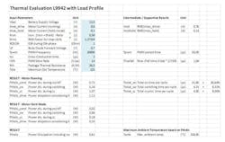
The table shows results for a state of the art stepper motor driver, in this case the STMicroelectronics L9942. These drivers feature various configuration options to optimize an application to specific system requirements, such as configurable slew rates, configurable PWM frequency, current regulation modes (current decay modes) for specific driver requirements, and configurable timings (blanking time, cross-current protection time). This is the basic requirement for an appropriate and robust thermal system design and allows the developer to evaluate and optimize application parameters with different device configurations.
