
This file type includes high resolution graphics and schematics when applicable.

Today’s electronic devices have higher mobility and are greener than ever before. Battery advances are fueling this progression in a wide range of products, from portable power tools to plug-in hybrid electric vehicles to wireless speakers. In recent years, battery efficiency—the amount of power a battery can output with respect to size and weight—has dramatically improved.
Think about the weight and bulkiness of a car battery. Its main purpose is to start the car. With recent advances, however, you can now jumpstart your car with a lithium-ion battery, which is the size of your hand and weighs only a couple of pounds.
Perpetually transforming battery technology has prompted many newcomers to become knowledgeable in battery-management system design. This article provides a beginner’s guide to the battery-management-system (BMS) architecture, discusses the major functional blocks, and explains the importance of each block to the BMS system.
Battery-Management-System Architecture
A battery-management system (BMS) typically consists of several functional blocks, including cutoff field-effect transmitters (FETs), fuel-gauge monitor, cell-voltage monitor, cell-voltage balance, real-time clock, temperature monitors, and a state machine (Fig. 1). Several types of BMS ICs are available.
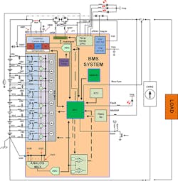
The grouping of functional blocks vary widely from a simple analog front end, such as the ISL94208 that offers balancing and monitoring and requires a microcontroller, to a standalone integrated solution that runs autonomously (e.g., the ISL94203). Now let’s examine the purpose and technology behind each block, as well as the pros and cons of each technology.
Cutoff FETs and FET Driver
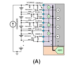
A FET-driver functional block is responsible for the battery pack’s connection and isolation between the load and charger. The FET driver’s behavior is predicated on measurements from battery-cell voltages, current measurements, and real-time detection circuitry. Figure 2 illustrates two different types of FET connections between the load and charger, and the battery pack.
Figure 2A requires the fewest number of connections to the battery pack and limits the battery pack operating modes to either charge, discharge, or sleep. The current flow direction and the behavior of a specific real-time test determine the device’s state.
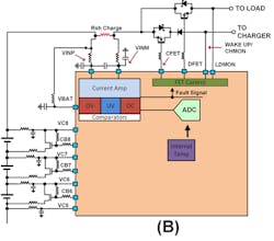
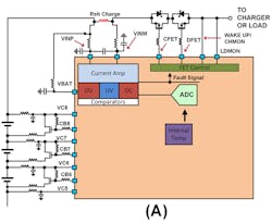
For example, the ISL94203 has a channel monitor (CHMON) that monitors the voltage on the right side of the cutoff FETs. If a charger is connected and the battery pack is isolated from it, the current injected toward the battery pack will cause the voltage to rise to the charger’s maximum supply voltage. The voltage level at CHMON is tripped, which lets the BMS device know a charger is present. To determine a load connection, a current is injected into the load to determine if a load is present. If the voltage at the pin does not rise significantly when injecting current, the outcome determines that a load is present. The FET driver’s DFET then turns on. The connection scheme in Figure 2B allows the battery pack to operate while charging.
FET drivers can be designed to connect to the high or low side of a battery pack. A high-side connection requires a charge-pump driver to activate the NMOS FETs. When using a high-side driver, it allows for a solid ground reference for the rest of the circuitry. Low-side FET driver connections are found in some integrated solutions to reduce cost, because they don’t need a charge pump. They also don’t require high-voltage devices, which consume a larger die area. Using the cutoff FETs on the low side floats the battery pack’s ground connection, making it more susceptible to noise injected into the measurement. This affects the performance of some ICs.
Fuel-Gauge/Current Measurements
The fuel-gauge functional block keeps track of the charge entering and exiting the battery pack. Charge is the product of current and time. Several different techniques can be used when designing a fuel gauge.
A current-sense amplifier and an MCU with an embedded low-resolution analog-to-digital converter (ADC) is one current-measurement method. The current-sense amplifier, which operates in high common-mode environments, amplifies the signal, enabling higher-resolution measurements. This design technique sacrifices dynamic range, though.
Other techniques use a high-resolution ADC, or a costly fuel-gauge IC. Understanding the load behavior’s current consumption versus time determines the best type of fuel-gauge design.
The most accurate and cost-efficient solution is to measure the voltage across a sense resistor using a 16-bit or higher ADC with low offset and high common-mode rating. A high-resolution ADC offers a large dynamic range at the expense of speed. If the battery is connected to an erratic load, such as an electric vehicle, the slow ADC may miss high-magnitude and high-frequency current spikes delivered to the load.
For erratic loads, a successive-approximate-register (SAR) ADC with perhaps a current-sense amplifier front end may be more desirable. Any offset error affects the overall error in the amount of battery charge. Measurement errors over time will cause significant charge status battery-pack errors. A measurement offset of 50 µV or less with 16-bit resolution is adequate when measuring charge.
Cell Voltage and Maximizing Battery Lifetime
Monitoring the cell voltage of each cell in a battery pack is essential to determine its overall health. All cells have an operating voltage window where charging/discharging should occur to ensure proper operation and battery life. If an application is using a battery with a lithium chemistry, the operating voltage typically ranges between 2.5 and 4.2 V. Voltage range is chemistry-dependent. Operating the battery outside the voltage range significantly reduces the lifetime of the cell and can render it useless.
Cells are connected in series and parallel to form a battery pack. A parallel connection increases the battery pack’s current drive, while a series connection increases the overall voltage. A cell’s performance has a distribution: At time equal zero, the battery-pack cell’s charge and discharge rates are the same. As each cell cycles between charge and discharge, each cell’s charge and discharge rates change. This results in a spread distribution across a battery pack.
A simple way to determine if a battery pack is charged is to monitor each cell’s voltage to a set voltage level. The first cell voltage to reach the voltage limit trips the battery-pack charged limit. A weaker-than-average cell battery pack results in the weakest cell reaching the limit first, keeping the rest of the cells from fully charging.
A charging scheme, as described, doesn’t maximize the battery-pack ON time per charge. The charging scheme reduces the battery pack’s lifetime because it needs more charge and discharge cycles. A weaker cell discharges faster. The also occurs on the discharge cycle; the weaker cell trips the discharge limit first, leaving the rest of the cells with charge remaining.
There are two ways to improve the ON time per battery pack charge. The first is to slow the charge to the weakest cell during the charge cycle. This is achieved by connecting a bypass FET with a current limiting resistor across the cell (Fig. 3A). It takes current from the cell with the highest current, resulting in a slowing cell charge. As a result, the other battery pack cells are able to catch up. The ultimate goal is to maximize the battery pack’s charge capacity by having all of the cells simultaneously reach the fully charged limit.
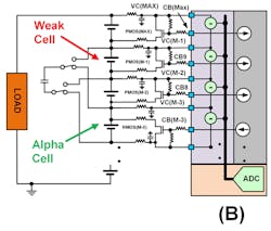
The second method is to balance the battery pack on the discharge cycle by implementing a charge-displacement scheme. It’s achieved by taking charge via inductive coupling or capacitive storage from the alpha cell and injecting the stored charge into the weakest cell. This slows the time it takes the weakest cell to reach the discharge limit, otherwise known as active balancing (Fig. 3B).
Temperature Monitoring
Today’s batteries deliver lots of current while maintaining a constant voltage. This can lead to a runaway condition that causes the battery to catch fire. The chemicals used to construct a battery are highly volatile—a battery impaled with the right object can also make the battery catch fire. Temperature measurements aren’t just used for safety, they also can determine if it’s desirable to charge or discharge a battery.
Temperature sensors monitor each cell for energy-storage-system (ESS) applications or a grouping of cells for smaller and more portable applications. Thermistors powered by an internal ADC voltage reference are commonly used to monitor each circuit’s temperature. In addition, an internal voltage reference helps reduce inaccuracies of the temperature reading versus environmental temperature changes.
State Machines or Algorithms
Most BMS systems require a microcontroller (MCU) or a field-programmable gate array (FPGA) to manage information from the sensing circuitry, and then make decisions with the received information. In certain devices, such as the ISL94203, an algorithm that is digitally encoded enables a standalone solution with one chip. Standalone solutions are also valuable when mated to an MCU, because the standalone’s state machine can be used to free up MCU clock cycles and memory space.
Other BMS Building Blocks
Other functional BMS blocks may include battery authentication, real-time clock (RTC), memory, and daisy chain. The RTC and memory are used for black-box applications—the RTC is used as a time stamp and memory is used for storing data. This lets the user know the behavior of battery pack prior to a catastrophic event. The battery authentication block prevents the BMS electronics from being connected to a third-party battery pack. The voltage reference/regulator is used to power peripheral circuitry around the BMS system. Finally, daisy-chain circuitry is used to simplify the connection between stacked devices. The daisy-chain block replaces the need for optical couplers or other level-shifting circuitry.
This file type includes high resolution graphics and schematics when applicable.
Conclusion
Battery-management systems can be built using a plethora of functional blocks and design techniques. Careful consideration of battery requirements and battery-life goals will help determine the right architecture, functional blocks, and related ICs to create a battery-management system and charging scheme that optimizes battery life. For more information about battery-management solutions, go here.
About the Author
Ryan Roderick
Principal Electrical Engineer, Precision Products Group
Ryan Roderick, principal electrical engineer for the Precision Products Group at Intersil Corp., previously served as an electrical engineer in Analog Devices Inc.’s Advanced Linear Products Group, and as a design engineer at Biode Inc., researching the use of piezoelectric sensors in aquatic and other liquid environments. He holds a BSEE and MSEE from the University of Maine, and is a patent holder, co-author of an IEEE paper, and author of several trade magazine articles.
Comment About the Article
To join the conversation, and become an exclusive member of Electronic Design, create an account today!

Leaders relevant to this article: