Passive Components Aren’t Really So Passive (Part 1): Capacitors
Download this article in .PDF format
This file type includes high resolution graphics and schematics.
Transistors and ICs are considered active components because they change signals using energy from the power supply. Capacitors, resistors, inductors, connectors, and even the printed-circuit board (PCB) are called passive because they don’t seem to consume power. But these apparently passive components can, and do, change the signal in unexpected ways because they all contain parasitic portions. So, many supposedly passive components aren’t so passive.
The Not-So-Passive Capacitor
Passive can be defined as inert and/or inactive. But passive electronic components can become an active part of a circuit in unexpected ways. Consequently, a capacitor that is purely capacitive simply does not exist. All capacitors inherently have parasitic components.
The active parasitic components in a capacitor are depicted in Figure 1. The capacitor labeled “C” is the one thing that we would like to see. The rest of the components are unwanted parasitics.1 The parallel resistor, RL, causes dc leakage that can change the bias voltage of the active circuits, spoil the “Q” in filters, and defeat the holding ability of a sample-and-hold circuit.2
A series resistor, ESR, reduces the capacitor’s ability to reduce ripple and pass high-frequency signals because the series inductance, ESL, creates a tuned circuit (i.e., a circuit with self-resonance). This means that above the self-resonance frequency, the capacitor looks inductive and can no longer decouple high-frequency noise from the power supply to ground.
The dielectric can be piezoelectric, adding noise from vibration (AC) that would resemble a battery inside the C capacitor (not depicted). The piezoelectric effect caused by the stress of cooling solder can alter the value of the capacitor. Polarized electrolytic capacitors can also have parasitic diodes in series (not shown), which can rectify high-frequency signals, alter bias, or introduce unwanted distortion.
The small batteries SB1 through SB4 indicate Seebeck junctions3 where dissimilar metals (parasitic thermocouples) create voltage sources. When we connect our test equipment, we need to consider the Seebeck effect of common connectors. Jim Williams’ application4 in Appendix J, figure J5 shows that the thermoelectric potential of pairs of BNC and banana connectors ranges from 0.07 µV/°C to 1.7 µV/°C. This variance is just for a simple connection that we do every day in the lab. Multiply that seemingly small offset gain by 1000 and we have 1.7 mV before we actually do anything productive.
SB2 and SB3 could be inside the capacitor where foil connects to the leads or the metallization connects to the plating or solder in a surface-mount part. SB1 and SB4 indicate the junction from the part through the solder to the copper PCB trace. Solder was once simple 63% lead and 37% tin. But today one has to ask for the contents of the alloy because lead-free Restrictions on Hazardous Substances (RoHS) solders can vary greatly and influence the voltage around the capacitor.
Dielectric absorption (DA), or what Bob Pease called “soakage,” can be modeled as an infinite number of different RC time constants, DA1 through DAInfinity. Each of those time constants comprises a resistor, RDA, and a capacitor, CDA. Bob Pease gave us some practical examples of when “soakage” matters (see “Dielectric Absorption, Soakage, And Voltage Discharge From A Supposedly Passive Capacitor”).
“Well, if you turn your color TV off and open up the back, what’s the first thing you have to do before you start working on it? Put a grounding strap on a screwdriver and reach under the rubber shroud on the HV plug to discharge the CRT. OK, now that capacitance has been discharged, how much voltage will ‘soak’ back into the ‘capacitance’ of the picture tube if you let it sit for about 10 minutes? Enough to make a visible arc when you discharge it the SECOND time,” Pease said. “Now that’s what I call dielectric absorption.”5
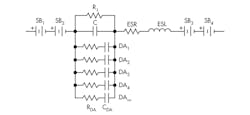
Fig. 1. In capacitor C and its largest parasitic components, each parasitic is unavoidable and degrades the wanted capacitor characteristics. The choice of the capacitor chemistry and construction can minimize some parasitics.
So capacitors can change capacitance with applied voltage. Then add typical aging, temperature dependence, and the many ways that capacitors can be physically damaged,6 and this simple passive component becomes far more complex.
Self-resonance is the most common capacitor issue with decoupling capacitors and poor grounds. No capacitor can do its job if the ground is poor. Capacitance self-resonance is dominated by the effect of the equivalent series inductance (ESL). But don’t discount the effect of the PCB vias either. At radio frequencies, those vias will affect the self-resonance point of small capacitors.
The 1-µF trace in Figure 2 finds a minimum at 4.6 MHz. Above that frequency, the ESL dominates and the capacitor operates like an inductor. This tells us that the decoupling capacitor is a two-way conduit for high frequencies: high frequencies on the power bus are shared with the ground, and vice versa. The capacitor homogenizes the difference between the power and ground.
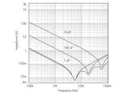
Fig. 2. The self-resonance of three capacitors can be found in the lowest point on the graph, showing that not all capacitors perform identically. On the left side, as the traces (impedances) move downward, the capacitors act as capacitors. But when they reach their lowest point and start upward, they become inductors (ESL) and are no longer effective as decoupling capacitors.
Thinking more about signal frequencies and capacitors, we might forget about the harmonics or sideband that we create. For example, a real 50-MHz square-wave serial peripheral interface (SPI) clock will have odd harmonics to infinity. Most systems, but not all systems, can ignore harmonics above the fifth harmonic because the energy is so low that it is below the noise floor. However, the harmonics can still cause problems if they become rectified in a semiconductor and can be transformed into new lower-frequency interference.
Manipulating The Manufacturing Tolerances in Capacitors
Figure 2 shows that not all capacitors are created equal. In general, high-quality capacitors are quite repeatable, while some inexpensive capacitors can trade large manufacturing tolerances for lower cost. Some manufacturers “bin” or select capacitors with a tight tolerance and that will sell for a premium price (Fig. 3). This can be detrimental if that capacitor is used to set a time or frequency in the system.
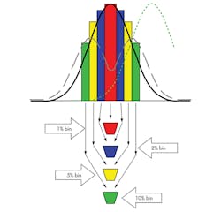
Fig 3. Binning, or sorting, of manufacturing tolerances will affect capacitor performance in different ways.
The solid (black) curve in Figure 3 is the standard deviation of a good manufacturing process. Although we used this illustration for resistors in Maxim Integrated’s application note 4301,7 the data apply equally for capacitors. As the manufacturing tolerances move, the number of parts in each bin changes. The tolerance could move to the right (the green dotted line), resulting in no yield at 1% tolerance. It could be bimodal (gray dashed line) with many 5% and 10% tolerance parts and few 1% and 2% tolerance parts.
Binning “seems” to ensure that the 2% tolerance parts are only from –1 to –2 and +1 to +2 (i.e., no 1% parts). It also “appears to” remove any 1% and 2% tolerance parts from the 5% bin. We say “seems to” and “appears to” because sales volume and human nature also influence the mix. For example, the plant manager may need to ship 5% tolerance capacitors, but he does not have enough to meet the demand this month. He does, however, have an overabundance of 2% tolerance parts. So, this month he throws them into the 5% bin and makes the shipment. Clearly deliberate human intervention can and does skew the statistics and method.
What does this mean for our passive capacitors? We must understand that the tolerance we might expect, for example ±5%, may have a ±2% hole in the middle. We need to allow for this if the capacitor controls a critical frequency or timing. It also could mean that we need to plan on correcting wider variation with calibration.
How Soldering Can Influence Passive Performance
Soldering introduces stress in the capacitors, and especially in surface-mount parts. That stress can cause piezoelectric voltages with vibration and even crack the capacitor so it later fails. Proper reflow soldering is impressive. The surface tension of the melting solder causes the parts to rotate into alignment as if by magic. But poor solder-temperature profiles can really damage the device.
Have you seen capacitors stand up on one end like a tombstone? This can happen if the solder temperature ramp is wrong. Always follow the manufacturer’s solder-profile recommendations. Some components are more sensitive to temperature, so the board assembly may require two or more solders with different melting temperatures.
Most components in a circuit are soldered first with the highest melting point solder and then any “sensitive” component is soldered at lower temperatures. The solders must be used in the right order so those parts soldered early in the process are not unsoldered later.
The Capacitor: A More Active Component Than It Appears
When we discuss passives like capacitors, we must remember that these devices all contain parasitic portions that can change a signal. The impact of this, of course, depends on the signal strength. If we want to measure microvolts, then everything counts: grounding (star points), shielding decoupling capacitors, guarding, layout, the Seebeck effect, cable construction, and soldering connectors. Our schematics usually gloss over this, which is acceptable until we are looking for small noise or voltages.
Remember that a passive capacitor is just one component and really more active than it appears. There are subtle effects of component parasitics, tolerance, calibration, temperature, aging, and even assembly methods and practices that will influence the device’s performance. Knowing that, we need to understand the potential errors that can accumulate with numerous capacitors. In future articles we will discuss other so-called passive components, resistors, potentiometers, switches, and, surprisingly, the lowly PCB.
Finally, AVX and Kemet are capacitor companies that specify parasitic components and provide free Spice tools.8 These tools allow us to graph the actual performance of the capacitors. The application notes on both their websites are also very informative.
References
1. Capacitor Distortion Mechanisms www.co-bw.com/Audio_Capacitor_Distrotion_Mechanisms.htm. (The word “distrotion” in this URL is misspelled, but the URL is correct as shown.)
2. Pease, Bob, “What’s All This Capacitor Leakage Stuff, Anyhow?” Electronic Design, March 29, 2007, http://electronicdesign.com/analog/whats-all-capacitor-leakage-stuff-anyhow.
3. Jim Williams used an “x” to indicate a Seebeck junction. He would count the junction in parallel paths and purposely cut the PC trace and solder them back together to make equal numbers of junctions. See Williams, Jim, et al, application note 86; “A Standards Lab Grade 20-Bit DAC with 0.1ppm/°C Drift,” http://cds.linear.com/docs/en/application-note/an86f.pdf. See also Pease, Bob, “Understand Capacitor Soakage to Optimize Analog Systems,” http://portal.national.com/rap/Application/0,1570,28,00.html. For more general information on Seebeck junctions, you can start at http://en.wikipedia.org/wiki/Thermoelectric_effect.
4. Williams, Jim, op cit.
5. Pease, Bob, “What’s All This Soakage Stuff, anyhow?” Electronic Design, May 13, 1998, http://electronicdesign.com/analog/whats-all-soakage-stuff-anyhow.
6. Maxwell, John, AVX Corp., “Technical Information, Cracks: The Hidden Defect,” http://www.avx.com/docs/techinfo/cracks.pdf.
7. Maxim Integrated, application note 4301, “The Zero-Transistor IC, a New Plateau in IC Design,” www.maximintegrated.com/AN4301.
8. Spice tools for Kemet and AMX capacitors can be found near the bottom of the page at www.maximintegrated.com/cal.
This file type includes high resolution graphics and schematics.
About the Author
Bill Laumeister
Bill Laumeister is an engineer in strategic applications at Maxim Integrated Products. He works with customers who use Maxim’s analog and digital integrated circuits. He has more than 30 years of experience and holds several patents.
Comment About the Article
To join the conversation, and become an exclusive member of Electronic Design, create an account today!

Leaders relevant to this article: