This file type includes high-resolution graphics and schematics when applicable.
The endlessly creative art of marketing is a powerful tool that helps companies highlight their differentiations and advantages over industry competitors. However, do these supposed advantages make a difference in your particular application? Does it really matter if the product of interest is smaller, faster, stronger? As it turns out, like most things in life, the answer is “it depends.”
This article will attempt to look beyond typical marketing specifications to truly understand some of the key differences in point-of-load (POL) dc-dc converter performance and how they relate to your specific system design. Specifically, we will look at efficiency, output capacitance, compensation schemes, and cooling requirements.
Peak Efficiency vs. Efficiency Under Real-World Loading Conditions
The efficiency of power converters is typically denoted by the lowercase Greek letter eta (η), and is expressed as the ratio of power delivered to the output relative to the power consumed by the input (η = POUT/PIN). The ideal ratio, or efficiency, of any converter is 1. This indicates that 100% of the power coming into the converter is delivered to the load with zero loss. In real-world applications, though, there will always be some loss/inefficiency associated with converting energy from one form to another, which will reduce the η from 1 down to something less.
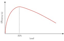
Knowing that 100% efficiency is ideal, marketing teams often tout their highest achievable conversion efficiency possible in an attempt to stand out as the “best” for your application. This is often referred to as the “peak efficiency.” The challenge is that efficiency isn’t just a single number, but rather a multi-variant function that’s typically expressed as a function of output current/power delivered to the load. To illustrate how efficiency is affected by output load, Figure 1 shows a hypothetical example of a point-of-load efficiency curve.
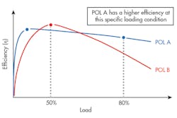
In this hypothetical example, the peak of the efficiency curve occurs when the output load is at 50% of full load. At light loads, the efficiency is much lower; at loads beyond the peak, the efficiency gradually declines. It’s important to understand these curves when designing a power-delivery system because operating at any load above or below the peak efficiency point will result in wasted power and unwanted heat in your system. Figure 2 shows that although POL B has the higher peak efficiency, POL A is the preferred choice for this application (in terms of efficiency) due to the amount of power demanded by the load.
Achieving Desired Ripple/Transient Performance
Another metric of interest with POL converters is the amount of added system-level capacitance required to arrive at the desired ripple and transient performance. Details surrounding the theory of external capacitor quantity and type are beyond the scope of this article, but it should be noted that not all POL modules are created equal when it comes to performance—even if the datasheets present similar numbers.
On the surface, it may appear that different POLs have similar ripple and transient performance. However, by digging deeper into the test conditions, you will often see big differences that can affect the overall cost and size of your power-delivery solution.
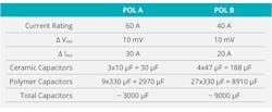
Figure 3 is a comparison of two competing POL modules. From the datasheets’ high-level marketing bullet-point numbers, these two potential solutions look to be fairly identical in terms of ripple and noise.
However, when analyzing the fine print, we see that one of the modules (POL B) requires 300% more external capacitance to achieve the same voltage deviation performance as the other. This represents a significant amount of added cost and under-utilized board space.
Fortunately, more advanced POL modules now offer full digital implementations. They bring significant improvement over traditional analog modules in terms of ripple/transient performance relative to the size of the overall solution.
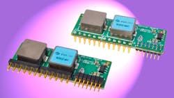
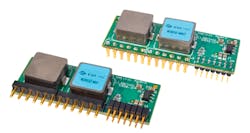
The CUI NDM3Z-90 series (Fig. 4) is an example of one such solution. It delivers up to 90 A of current to the load with good ripple/transient performance, often with a significant reduction in output capacitance.
Compensation Schemes
A point-of-load module provides a stable and regulated output in an attempt to produce a clean voltage rail to its load. This implies that the POL inherently contains a negative feedback loop. Therefore, whenever a deviation from the ideal output occurs, the POL’s feedback network will compensate and attempt to bring the output back into ideal regulation.
Many different nuanced compensation schemes are available in the market, but below we will review the high-level strengths and weaknesses surrounding common analog- and digital-compensation schemes.
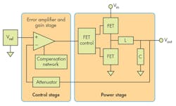
• Analog compensation: In an analog-compensation network, the output of the module is sensed, filtered, and compared to a reference voltage to generate an error signal. This error signal is used to compensate the output and correct any deviations that may have occurred (Fig. 5).
The advantage with analog-compensation schemes is that they have been around for a long time and can be implemented using standard off-the-shelf components. The drawback with such schemes is that it can be quite challenging to “tune the loop” to be stable across all operating conditions while maintaining a wide bandwidth for a fast transient response. This typically requires many hours in the lab to do soldering, testing, re-soldering, re-testing, etc. Analog-compensation schemes are also susceptible to picking up external noise, which could inadvertently be coupled to the output.
Although the analog compensation scheme and its many variants have been the standard for quite some time, there are newer digital compensation schemes that have come along in the last decade or so, which offer some significant advantages.
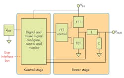
• Digital compensation: Similar to analog schemes, a digitally compensated implementation senses the output, filters it, compares it to a reference, generates an error, and ultimately compensates the output to correct any deviations that may have occurred (Fig. 6).
The major difference is that all of this is done in the digital domain with 1s and 0s. The “sensing” of the output is accomplished with an analog-to-digital converter, and then all of the comparing, error-generation, and compensation is done digitally inside an integrated circuit (IC). Operating within the digital domain also significantly improves noise rejection, which helps prevent inadvertent coupling of external noise sources to the output.
Utilizing a digital-compensation scheme means you no longer have to spend hours in the lab soldering different components to tweak the feedback loop. Instead, you can simply modify a few digital parameters within the IC and change the POL’s behavior to meet the needs of your application.
The more advanced digital POLs on the market today take this luxury one step further to offer “compensation-free” designs. In these designs, the POL makes all of the necessary measurements and adjustments for you in-system to continuously provide a fast-reacting and stable output-voltage rail.
Cooling Requirements
One of the biggest limiting factors in point-of-load modules is heat dissipation. Inefficiencies in the module’s design results in unwanted internal heat generation, causing critical components (e.g. FETs, inductors, capacitors, etc.) to approach their maximum rated operating temperature. Operation at or above these components’ thermal limits can reduce reliability and result in hardware failure.
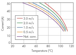
To combat the damaging effects of internal heat generation, POL vendors often recommend a minimum amount of airflow to draw heat away from the module. This prevents heat from building up inside the components and raising temperatures beyond their rated limits. Using airflow to remove heat from the module can often increase the amount of power that can be delivered to the load, as well as improve the ambient operating-temperature range. Figure 7 shows a POL module’s ability to operate in different airflow environments ranging from natural convection (still air) to 3 m/s.
7. Illustration of a typical derating curve under different airflow conditions.
We see that under natural convection (still air) conditions (denoted by the purple line in Fig. 7), the module can deliver 43 A to the load up to 60°C. Adding just 2 m/s of airflow increases both the current capacity and ambient operating-temperature range up to the full 50 A at 64°C ambient (denoted by the green line in Fig. 7). However, forced-air cooling does have its drawbacks—it consumes power, which can negate some of the efficiency gains, and can generate unacceptable levels of noise. Designers must carefully weigh the thermal requirements of the power module with the cooling capabilities of their system when selecting a POL.
Conclusion
Every application is different and values different performance metrics. For some, a fast transient response may be the most important consideration, while others may require the smallest size, highest efficiency, or widest operating-temperature range. No one POL can meet all of these requirements for each application, no matter what the marketing teams may tell you. It’s crucial to first understand your application’s needs under its specific operating conditions. Only then can you compare and select the optimal POL for your design.
This file type includes high-resolution graphics and schematics when applicable.
About the Author
Aaron Yarnell
Field Applications Engineering Manager
Aaron Yarnell joined CUI in 2014 as Field Applications Engineering Manager, where his responsibilities include customer-facing engineering support for CUI’s portfolio of products, technical writing, and product training. Prior to joining CUI, Aaron was the co-owner of Wizard Manufacturing Company, and was a senior FAE at Silicon Labs.
Aaron holds a Bachelor’s in Electrical Engineering, with a focus on analog circuit design, from the Oregon State University.
