Power Management Takes Off In Industrial Control
PoE classification scheme
Common Fieldbuses
Basic PoE and PoE-Plus
PMBus commands
The days of “dumb” industrial power supplies that simply hummed along pumping out amperes at fixed voltages are receding in the rear-view mirror. Intelligent power management, to mix an automotive metaphor, driven a little by green sensitivity and a lot by practical economics, is looming in the windshield as a critical tool in managing profit and loss. Two new and complementary modes of industrial power management deserve a close look: Power over Ethernet (PoE), particularly the PoE-Plus variety, and PMBus (“PM” for power management).
FROM THE FIELDBUSES
It may seem a little surprising to find Ethernet mentioned in the same breath as control systems. It’s also possibly somewhat strange to find PoE, originally conceived as a way to power Voice over Internet Protocol (VoIP) enterprise telephones, in a factory-control environment. Yet there is method to the madness.
Industrial networks connecting sensors, actuators, and the computers that monitor and control them have been largely implemented as fieldbuses (Table 1), which are industrial networks intended specifically for real-time monitoring and control (see “Networking Ignites The New Industrial Revolution”). They typically comprise a physical layer and a data protocol that accommodates basic control elements: sensors and actuators, plus programmable logic controllers (PLCs) and proportional integral differential (PID) controllers.
Fieldbuses evolved from early current-loop monitor and control systems that used analog techniques to measure and control devices remotely into faster and more sophisticated systems. However, they often were proprietary and weren’t interoperable with other fieldbuses.
On the positive side, these fieldbuses provided and continue to provide deterministic, hard-real-time control. On the negative, they are architecturally primitive and challenging to implement at higher levels of complexity.
As industrial control networks evolve into formal networks populated with large numbers of sensors and controlled devices, industrial control using Ethernet (IEEE 802.3) grows in appeal. It is the standard for data-communications networks. Also, economies of scale make Ethernet servers, switches, and software relatively cheap, given the high sophistication of their functionality. Most attractively, Ethernet provides software hooks not only for monitoring and control, but for data collection and analysis and even for accounting functions as well.
Ethernet is not determininstic, though. But that isn’t always essential, as there are often workarounds. And when hard real-time control is essential, such as when interrupts must be serviced in 100% predictable fashion, fieldbuses that can interoperate with Ethernet provide targeted solutions for those control loops.
PoE EVOLUTION
Basic PoE began with Cisco’s proprietary approach for powering VoIP business phones over twisted-pair Ethernet cable. When Cisco opened up the standard, an IEEE 802.3 task force began to work on what became the IEEE 802.3af baseline PoE standard. PoE uses either the data pairs or the “spare” pairs in the cable to carry 48 V dc from the switch or midspan hub to the appliance at the other end of the cable. Data pairs are powered via center tap, while spare pairs are simply paralleled. The sense of the dc voltage doesn’t matter, thanks to a diode bridge ahead of the appliance-controller chip.
When work on 802.3af began, designers still didn’t know how much current a maximum-length CAT5 cable (or more critically, the RJ45 connectors on the ends of the cable) could handle. So, power was limited to 15 W (at 48 V dc) at the powered end of the cable, where the power source equipment (PSE) resides. That limitation in turn affected the powered device (PD) at the other end of the cable.
In terms of power management, basic PoE provided only a limited range of capabilities. (At this point, we’re only talking about PoE and office appliances.) That limited scope arose in response to observations that not every node in an Ethernet network in an office environment needed to be powered over its CAT5 cable. Moreover, even the devices at those nodes did not all need a full 15 W all the time.
Furthermore, an Ethernet switch (or a bridge, if one were powering an existing Ethernet network) with a big enough power supply to deliver 15 W to each circuit would carry far too high a price premium. The solution was a simple fixed-resistor “discovery” and “classification” scheme, by means of which PDs would inform the PSE of their maximum current needs when they were plugged in.
Under the basic standard, PSEs can apply power to the Ethernet cable if there’s a PoE-PD on the other end. The PSE does this by checking for the presence of a 25-kΩ resistor in the PD. To “discover” the presence of a PoE PD, the PSE applies two voltages (separated by 1 V and a 20-ms interval) and uses the resulting currents to determine the resistance value.
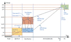
The subsequent “classification” phase is optional. The point of the classification is to enable the PSE to determine whether it has enough capacity to supply the PD. During classification, the PSE briefly asserts a 15.5- to 20-V pulse on the pair, In response to the pulse, the PD may do nothing, or it can opt to signal the PSE by placing a load on the line. That tells the PSE the PD’s maximum current needs: 400, 300, 210, or 120 mA.
The 15-W limit at the PSE proved to be a problem almost from the start, because 15 W (actually 13 at the PD) was not enough power for a new generation of enterprise VoIP phones, which featured teleconferencing and needed more power for their video screen backlighting. Also in need of more power were pan/zoom/tilt surveillance cameras and Wi-Fi nodes, which were being touted as breakthrough applications areas for PoE, if only more power were available. Thus, the IEEE began work on a higher-powered PoE known as PoE-Plus, or more formally, IEEE 802.3at (Table 2).
The 802.3at task force then enhanced the basic PoE classification scheme (see the figure). Under PoE-Plus, all PSEs (base-spec and Plus) send the first classification pulses. PoE Plus PSEs also send a second pulse. Standard PoE PDs respond in the usual fashion to the first pulse, and that’s that. PoE-Plus PDs respond by asserting a resistive load that was “reserved” in the basic standard. They thereby identify themselves as what the standard calls “Class 4.”
If the PSE sends the second pulse, both the switch and the appliance now are aware that more than 15 W is available. At this point, they both abandon primitive resistive semaphore signaling and go digital, using PoE-Plus’s Link-Layer Data Protocol (LLDP) for negotiation.
What does this achieve in an industrial control context? It’s too early in the game to know all the advantages. But a white paper (registration required) from Akros Silicon, a chip maker that provides PSE and PD chips as well as a complete reference design for evaluation, considers some possibilities in terms of data centers.
The paper says that one of the PoE Plus enhancements “is the ability to control power distribution in much finer detail than with the existing standard.” PoE Plus addresses the growing demand for enterprise “green power” initiatives, such as more efficient use and intelligent allocation of power, as well as a reduction in the overall energy footprint.
DYNAMIC CONTROL
Considering the ability to use Layer-2 software communication to query each PD to dynamically determine peak and average power requirements, the paper notes that in the enterprise, for example, VoIP phones don’t require steady availability of the 6.5 W or 13 W that are allocated to them via initial PSE/PD classification. They can be reduced to a much lower standby power and quickly ramp up to their active power level upon the initiation of a call or other wakeup event.
“Similarly, IP (Internet protocol) cameras working in low light, generating high-definition IP video streams of rapidly moving objects, might only require its maximum 25.5-W allocation during a midnight alarm condition, likely when the VoIP phone usage is minimal. So power to the VoIP ports can be reallocated to the IP camera ports after business hours,” the paper says. It’s quite easy to imagine similar scenarios in the industrial control context.
PMBus
PMBus provides a different but complementary standard for industrial power-supply control. It’s two-wire. It’s deterministic. And, it provides very fine-grained power-supply control and monitoring.
“The PMBus was founded in October 2004 by Artesyn Technologies (now part of Emerson Network Power), along with no less than six of the world’s top semiconductor manufacturers,” says Bob White of Embedded Power Labs. White also worked at Artesyn Technologies when the PMBus was established, and he has been its most visible champion since its inception.
PMBus was primarily designed to be applied to power management in data centers, because that area was expected to see the highest benefits in 2004. Implementation has proven slower than hoped for in that arena, but the concept has not been abandoned (see “PMBus Takes Command of Data Center Power Issues” at http://powerelectronics.com). In the time since work on PMBus began, a broader interest in power management for industrial control has arisen, particularly in the last year or so.
PMBus defines the transport and physical interface, as well as the command language, needed to accomplish digital power management. The PMBus transport layer is based on version 1.1 of Intel’s System Management Bus (SMBus), which in turn is based on Philips’ I2C serial bus with packet error-checking and host-notification features. SMBus was chosen because it is widely used in Intel-based servers, where it provides the physical and transport layers of the Intelligent Peripheral Management Interface (IPMI) employed for system management.
Beyond the two wires of I2C, SMBus offers a third signal line, designated SMBAlert#, that allows slave devices to interrupt the system host/bus master. Such an interrupt-driven system facilitates response determinism and unburdens the host processor, making it easier for designers to implement event-driven closed-loop control schemes.
When a limit threshold has been exceeded, the PMBus supply or converter asserts SMBAlert# by pulling that line low. The system responds by sending the Alert Response Address to all the power converters on that SMBus branch. Then, the converter that asserted the SMBAlert# line responds with its address and releases the alert line.
For power-conversion devices, the PMBus protocol also specifies two hardwired signals. One is a write-protect signal that can be used to prevent any changes to memory-held data. The other is a control signal for turning individual slave devices on and off. PMBus also requires slave devices to either store their default configurations in nonvolatile memory or to be pin programmable, so startup time is short.
Command packets comprise an address byte; command byte; zero, one, or more data bytes; and an optional packet error code (PEC) byte. Typically, the host uses single “start” and “stop” conditions, and the addressed client device responds via a single “acknowledge” bit. There is no “execute” command. A slave processes and executes as soon as it receives a stop bit.
SOME COMMANDS
PMBus commands for this kind of use can be categorized into three areas: power sensing, thermal management, and diagnostics. For sensing power consumption in system power converters, PMBus offers commands (Table 3) to read power-in and out and read current in and out. Data is represented in the form:
X = Y × 2N
Here, Y, the mantissa, is an 11-bit two’s complement integer, representing the least significant bits. N, the exponent defining scaling, is a 5-bit two’s complement integer representing the most significant bits. It’s a constant for any particular power supply. From Y and N, the system can determine the real-world value of X.
POWER-MANAGEMENT SPECIFICS
What are we actually talking about in terms of power management in industrial control? There are parallels with the data center. “Understanding where and how much actual power is consumed at the data center, rack, system, and subsystem levels can help optimize data center power-delivery and cooling systems,” says Brian Griffith of Intel (see “PMBus Takes Command of Data Center Power Issues,” again).
One objective is to control temperatures by maximizing the available resources of systems, power distribution units (PDUs), cooling units, and uninterruptible power-supply (UPS) systems. (In the data center, there is also the opportunity to shift loads by virtualization.) This can be accomplished by using PMBus power sensors located in the power supply and on the motherboard.
Griffith notes that being able to determine the ac input power to the system power supply is particularly useful for power management. For example, it makes it possible to set do-not-exceed limits for system, rack, and overall power that managers can use to protect the facility from developing hot spots. In addition, monitoring the power consumed by each system gives managers a handle with which to deal with other resources such as air conditioners, power-distribution units, and UPSs in the data center or plant to make them more efficient.
For data centers, Griffith mentions “charge back” and notes that in co-located environments, managers may bill end users according to their contribution to the total system energy consumption. That’s another place to use data on ac input power. For this purpose, calculating the input power to the ac-dc power supply is a matter of multiplying instantaneous voltage and current on the ac wave shapes and averaging the resulting values over the charge-back time to obtain the average of the real input power to the power supply.
There are different ways of doing this. An arithmetic average requires summing the sensor data over the averaging period and dividing by the averaging period and so forth. This is simple but inaccurate if the load varies a lot. The alternative is to compute a running arithmetic average, based on saving all the sensor data points over the average period. This is accurate, but it requires some dedicated memory.
Similarly, there are multiple ways to calculate the rms input current and rms input voltage. For a rue rms calculation, all that is necessary is to save enough data points to constitute at least one cycle of ac and calculate the rms parameter value. For current, that would be:
Irms = √((X1 + X2 + ... + Xn)/n)
If it’s possible to sacrifice a little accuracy, one can read the parameter on the secondary side of the ac-dc converter and multiply the rectified average by 1.11, assuming the ac is a true sine wave.
The system can use data generated by the READ_POUT and READ_IOUT commands to determine the percent loading status of the system power supplies and downstream converters. The data also can be used in a power-management algorithm to assess how much power is going to different parts of the system.
THERMAL MANAGEMENT
Whether it is used in a data center or a factory, PMBus thermal management commands include fan monitoring, fan control, and temperature sensing. This is useful in cases where power-supply fans are also used to cool other components in the system.
For this to work, the system needs a way to control the fans based on the temperature of the system components they are cooling. For example, FAN_COMMAND_x (where x is a number from 1 to 4) is used to control as many as four fans in a power supply. Similarly, the READ_TEMPERTURE_x commands can be used to read up to three temperatures inside the power supply.
DIAGNOSTICS
Griffith notes that power supplies have relatively high failure rates. He also says that with more information available, it’s easier to determine and isolate the root causes of failures.
The STATUS_WORD command provides the first level of diagnostic information by offering a high-level summary of all fault and warning conditions. If more detailed information is needed, there is a second level of status commands, including STATUS_INPUT and STATUS_TEMPERATURE. Results of STATUS commands include:
• Input voltage: warns if the input voltage drops too low and indicates a fault if the input voltage drops below a minimum operating point
• Output voltage: provides a warning and a fault if the output voltage is out of the operating range
• Temperature: warns if the temperature is about to exceed its maximum operating point and indicates a fault if an excessive temperature caused the power supply to shut down
• Fan speed: warns if a fan is running too slow (indicating that it is wearing out) and indicates a fault if the slow-running fan caused the power supply to shut down.
• Output current: warns if the system has loaded a power supply to its maximum rating and indicates a fault if the overload caused the power supply to shut down.
About the Author

Don Tuite
Don Tuite (retired) writes about Analog and Power issues for Electronic Design’s magazine and website. He has a BSEE and an M.S in Technical Communication, and has worked for companies in aerospace, broadcasting, test equipment, semiconductors, publishing, and media relations, focusing on developing insights that link technology, business, and communications. Don is also a ham radio operator (NR7X), private pilot, and motorcycle rider, and he’s not half bad on the 5-string banjo.
Comment About the Article
To join the conversation, and become an exclusive member of Electronic Design, create an account today!

Leaders relevant to this article: