The use of rail-guided carriages dates back to hundreds of years before the industrial revolution. In 1825, the Stockton and Darlington Railway in the northeast of England became the world’s first public railway to use steam locomotives. By the 20th century, passenger and cargo transport operations could exploit more than 163,000 miles of track in the U.S. alone.
By mid-century, one might have predicted a virtual end to rail traffic due to rapid expansion of commercial aviation and growing highway systems. However, railroad use remains strong: Worldwide annual railway utilization exceeds 2 trillion passenger miles and 6 billion ton-miles of freight on over 850 thousand miles of track (Table 1).
Despite the ongoing high level of rail utilization, the market presents challenges to equipment providers and operators alike. The nominal operating life for diesel fleets is 30 years; 35 years for electric,1 with major refurbishment and upgrade around every 10 years.
This file type includes high resolution graphics and schematics when applicable.
Life on the Tracks
With such long equipment lifecycles, rolling stock manufacturers must be able to meet requirements of national and metropolitan rail networks anywhere in the world. As has been the case with the rest of the transportation sector, rail applications have adopted electronic technologies to improve safety, communication, reliability, and customer experience.
Rail services represent opportunities for large numbers of relatively low-volume electronic applications. Equipment manufacturers engaging this market benefit from maintaining common design elements as much as possible across a portfolio of products. Power subsystems represent one area of equipment design where such a strategy is practical.
Equipment for rail applications occupy four operating environments: rolling stock, lineside, platform, and terminal. Similar equipment may have applications in multiple environments and, thereby, may require different power subsystems. For example, LCD displays or discrete LED signage, operating on dc distribution power within a passenger carriage, can indicate approaching stations, announce delays, or provide time and weather information. The same equipment with a different power subsystem, drawing power from the ac mains, can provide information to passengers on platforms or within the terminal building.
Electronics for rail applications, particularly gear installed in rolling stock, must withstand harsh and variable operating conditions. These include shock and vibration, broad temperature ranges, rapid temperature shifts, wide-ranging source voltages, and EMI.
Despite the size of rolling stock, platforms, terminals, and the great outdoors that constitutes the trackside environment, railway applications demand power subsystems that occupy small volumes and provide high power density. Energy efficiency in the power subsystem and efficient energy utilization in the functional loads is desirable primarily because such characteristics minimize thermal-design challenges and improve reliability.
To extrapolate on that last point, reliability is a high priority in rail environments: Field failures are not just expensive; they can prevent detection of, or even cause, hazardous or lethal conditions.
Although various countries or regions impose their own standards for electronics operating on their rail networks, the trend has been to attempt to harmonize standards worldwide, as is the case in other technology sectors. The result, so far, falls well short of a single global set of requirements.
Nonetheless, pragmatic issues of economics and equipment availability have urged convergence in certain key measures of electrical compatibility and robustness. For these, the documents that serve as templates for many of the world’s numerous individual national or regional standards are EN-15055 (Railway Applications – Electronic Equipment Used on Rolling Stock) and EN-50121 (Railway Applications – Electromagnetic Compatibility).
EN-150155 defines four equipment classes according to operating temperature range (Table 2). Electrical-equipment cubicles on rolling stock are not temperature-controlled. In addition to meeting manufacturers’ performance specifications over wide operating temperature ranges, equipment must tolerate temperature shifts as large as 3°C/sec over variations as large as 40°C.
Except for equipment mounted within the temperature-controlled portions of a terminal, electronics for rail environments operate over the exterior temperature range. Within a single rail network, that can extend from subarctic winters to desert summers. Although EN-50155 applies specifically to rolling stock, the standard’s requirements can be useful when selecting components or subsystems for non-rolling-stock rail applications.
Supply Rails for Rail Apps
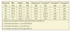
Railway standards recognize several nominal dc distribution voltages, typically 24, 48, 72, 96, and 110 V. EN-50155 allows liberal tolerances in distribution voltage, including 40% overvoltage transients (Table 3). Conforming equipment must perform as specified through transients not exceeding 100 ms, and sustain no damage from fluctuations between the maximum voltage and the transient voltage as long as 1 second. An example of similarities among industry norms can be seen in Great Britain’s RIA-12 and RIA-13 standards, which call for distribution voltage ranges that align with EN-50155 but impose more stringent transient voltage requirements.
With even modest margins, these requirements suggest a 16- to 160-V potential range in distribution voltage across all rolling-stock applications. Trackside, platform, and terminal applications differ in that they usually derive power from ac mains, which also exhibit wide variations in voltage.
In addition to the normal variations of the unregulated distribution voltage, equipment must tolerate low-energy, high-speed transient pulses, such as EN-50155’s 1.8-kV, 50-μs pulse, which falls within the capability of discrete transient suppressors. However, low-voltage, high-energy transients, such as RIA-12’s 20-ms test pulse at 3.5 times nominal voltage, derive from low source impedances—only 200 mΩ. Typically, these disturbances exceed the energy absorption limit of discrete suppressors, but may be addressed using active clamping circuits.
EN-50121 specifies limits for conducted and radiated EMI emission and susceptibility. Because power converters are sources of conducted and radiated EMI, due care should apply to power-subsystem design and layout to minimize RF emissions.
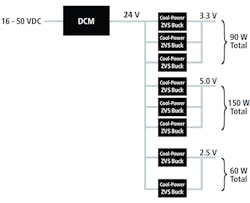
Rolling-stock distribution voltages vary to such an extent that the most practical power-subsystem architecture consists of two stages. The first stage provides galvanic isolation and regulates the distribution voltage to a Safety Extra Low Voltage (SELV) normalized potential of 60 V dc or less. The second stage(s)—step down the SELV output to voltages appropriate to the various functional loads. For example, Vicor’s DCM module isolates an unregulated input and exploits a high-frequency ZVS topology to provide a regulated 24-V nominal output, providing up to 320 W to downstream step-down converters such as Picor’s Cool-Power ZVS Buck ICs (see the figure).
The DCM’s ZVS topology provides high efficiency—up to 93%—and power density up to twice that of traditional hard-switched converters. Another advantage of the high-frequency ZVS converter topology is that it minimizes the power stage’s need for energy storage. Capacitor dielectrics that offer good temperature stability over EN-50155 temperature ranges exhibit low dielectric constants and, therefore, deliver comparatively poor volumetric efficiency. Minimizing the need for bulk capacitance in the power train saves cost, space, and susceptibility to shock-and-vibration-induced failure modes.
The two-stage approach provides significant benefits that shorten design cycles and overall time to market:
• Simplicity: The DCM and Cool Power ZVS Buck require few external components.
• Flexibility: Swap in different converter modules and buck converters to accommodate various input and output voltages. A small number of device models mix and match, minimizing inventory requirements and design-verification costs.
• Modularity: Parallel devices to deliver higher currents or swap an ac input module in place of the DCM for universal ac inputs like those for lineside, platform, or terminal applications.
Companies such as Vicor offer online design tools that help reduce design risk while shrinking design-cycle time. For example, Vicor’s PowerBench toolset allows users to quickly draw a power subsystem; get quick analysis of efficiency, power loss, footprint area, and cost; simulate individual components; and set configurations for user-defined power converters. Such capability reduces design cost and, importantly, design risk.
Conclusion
The array of electronic applications for rail networks continues to expand. The operating environments, however, are severe. Complicating matters for equipment providers are the many and varying conventions and national standards that apply to electronics destined for rail service, particularly in rolling stock. In this environment, the wide voltage tolerance on the unregulated dc distribution power feed poses challenges, particularly for power subsystem designs that must provide multiple voltage rails to functional loads.
This file type includes high resolution graphics and schematics when applicable.
With a two-stage architecture, designers can divide the problem to address source and load challenges independently. Combinations of DCM and Cool Power ZVS Buck converters exemplify this approach, combining simplicity, modularity, and flexibility to minimize design time, risk, inventory SKUs, and overall time to market while maximizing opportunities for design reuse.
References:
1. “Rolling stock requirements 2014—2019: An ATOC overview,” Association of Train Operating Companies, May 2012.
About the Author
Stephen Oliver
Vicor Corp., Power Design
Stephen Oliver, vice president of Vicor’s VI Chip Product Line, has been in the electronics industry for 18 years, with experience in applications engineering, product development, manufacturing, and strategic product marketing in the ac-dc, telecom, defense, processor power, and automotive markets. Previously with International Rectifier, Philips Electronics, and Motorola, he received a BSEE degree from Manchester University, the U.K., and an MBA in global strategy and marketing from UCLA. He holds several power electronics patents as well.


