Single 48V to 1V, 200A Converter Powers Microprocessors (Part 1)

Download this article in PDF format.
Microprocessors (µPs) and system-on-chip (SoC) integrated circuits impose very demanding large and fast load current changes of 10 A/µs to 50 A/µs yet require ultra-small transient voltage overshoot to settle very quickly. This is currently handled by up to 12 synchronous buck converters operating in parallel at 5MHz from 12V input, resulting in poor efficiency, large size, and high cost!
This legacy solution requires an intermediate bus converter (IBC) to convert 48V bus voltage to 12V. Some companies are attempting to eliminate such intermediate converters and provide a direct 48V to 1V, 200A converter. Besides using an inefficient two-stage conversion solution, all of these also fail to address fast load transient requirements other than using the multi-stage synchronous buck solution.
A direct 48V to 1V, 200A solution based on the new Hybrid Switching method and its implementation in novel converter topology employs a new magnetics structure designated the Hybrid transformer. The present µP drives all use the 12V to 1V legacy solution, since all other proposed 48V to 1V solutions cannot handle fast transients
One additional advantage of the described solution for 48V to 1V conversion is that it could be directly utilized for the present 12V, 1V µP drives by simply adjusting the transformer turns ratio and using appropriate lower-voltage-rated switching devices. This will also allow for a smooth transition from the present market of 12V to 1V to new, advanced 48V to 1V µP drives that will be needed in the near future.
Present Approaches
Besides just supplying the needed low 1V voltage, these power supplies must be able to handle large and fast load current changes of 10A/µs to 50A/µs, while requiring ultra-small transient voltage overshoots and the assurance that they settle very quickly. These demanding requirements result in unacceptable efficiency, large size, and high cost, even for a 12-V to 1-V conversion. Hence, a single 48V to 1V, 200A converter, which eliminates the IBC, is much preferred due to significantly reduced size, cost, and losses. The present efforts to accomplish this has centered on two approaches:
- Bridge-type transformer-coupled converters with some 8 to10 switches.
- Transformer-less converters with inductors and capacitors such as a Switched Tank Capacitor (STC) with 10 or more switches introduced and named so by Google at APEC 2017 and in patent US # 9917517B1 issued on March 13, 2018.
Both approaches have a common serious problem: They are inherently NOT capable to address the large dc load current change required by microprocessors. Both would still need additional multistage buck output stages to handle the load transients.
The STC converter isn’t even capable to convert to 1V nor to regulate output voltage. Despite its 10 transistor switches, it’s capable of fixed 4:1 step down only, such as from 48V to 12V with no regulation capability either!
For the first time, the above objectives are met in a converter with three switches only using a new Hybrid Switching Method. It uses a unique converter topology with a Hybrid transformer with sinusoidal currents.
Hybrid Switching Converter
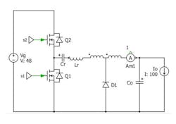
The basic Hybrid Switching converter circuit in Fig. 1 (top) answers the need for an efficient, small-size transient handling solution. Fig. 1 (bottom) is the timing diagram for the Hybrid Switching converter. Note that the converter has only two subintervals dictated by the ON and OFF intervals of the two active switches S1 and S2. It’s not just another ordinary pulse-width-modulation (PWM) converter using duty ratio control at a constant switching frequency.
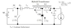
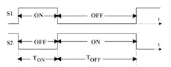
1. Basic Hybrid Switching converter (top) and timing diagram (bottom) for the Hybrid Switching converter (bottom).
As shown in Fig. 2, this converter incorporates a resonant inductor in series with the primary winding. This Lr inductor is NOT an external physical inductance—it represents the transformer’s leakage inductance. Leakage inductance is undesirable in transformers used with all conventional PWM and quasi-resonant converters because it stores energy that must be dissipated each cycle. This results in losses proportional to switching frequency and the square of the peak resonant current.
2. This simplified circuit shows the resonant inductor, Lr, that is in series with the primary winding of the Hybrid Switching converter.
In the Hybrid Switching converter, the transformer leakage inductance is a part of the basic operation of converter. It’s absorbed in the operation of the converter due to its resonance with the resonant capacitor Cr. Resonant current is always continuous and has no large current jump at switching intervals.
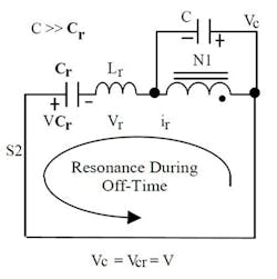
Fig. 3 shows the equivalent circuit during OFF time interval when the S2 switch and diode are conducting.
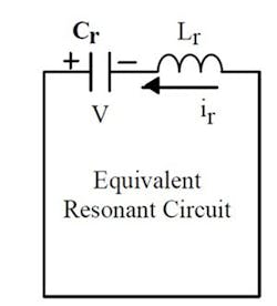
3. Equivalent resonant circuit of the Hybrid Switching converter.
Resonant inductance Lr must satisfy that the net (average) of its ac voltage vr must be zero in steady-state during the OFF time so that flux balance on vr results in:
resulting in:
Vcr = Vc = V (2)
Using this result and provided that:
C>> Cr (3)
the simplified equivalent resonant circuit is obtained as in Fig. 3 and the solution is:
Vcr = V sin (ωrt) (4)
icr = ip= −0.5 I cos (ωrt) (5)
is = I − 0.5 I cos(ωrt) (6)
Diode current is the sum of the primary and secondary currents:
iD = ip + is = I − cos(ωrt) (7)
Voltage Conversion Derivation
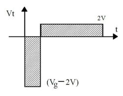
4. Rectangular voltage and flux (volt-second) balance.
From Equation 2, the flux balance on the 1:1 turns ratio transformer is obtained from the rectangular voltage waveform in Fig. 4.
(Vg -2V) D = 2V(1-D) (8)
and conversion gain is:
V = 0.5 D Vg (9)
In general:
V = DVg(N2/(N1 + N2) (10)
Hence, the voltage gain is the same as in the PWM forward converter operating with duty ratio, D, and transformer primary turns N1+N2 and secondary turns N2. Linear voltage gain with duty ratio D is confirmed by measurement.
Hybrid Transformer Resonant Currents
The Hybrid transformer is a close approximation of the Faraday transformer. It has an inherent feature that its primary and secondary currents are sinusoidal at the resonant frequency and are scaled by the transformer turns ratio. Moreover, their peak magnitudes are directly proportional to the dc load currents and therefore automatically scale up or down with the change of the dc load current. This directly leads to the load transient elimination in a fraction of a single switching period.
Converter Simulation Model
The converter is modeled using the .plecs simulation program from PLEXIM (Fig. 5).
5. Plecs simulation model.
This is the reason this converter makes it possible to eliminate large transients in a single switching period. Moreover, this is accomplished with a single module and doesn’t require 12 modules of the synchronous buck converters to obtain acceptable transient response.
Diode current waveforms exhibit another extraordinary feature. The diode as a switch is turned ON at zero current and turned OFF at zero current for all load currents. Hence, the diode switching losses are eliminated for any dc load currents from full load to no load due to zero current switching (ZCS). In fact, the diode doesn’t even know that it’s switching. It doesn’t even conduct any current during switching instances.
This also leads to another extraordinary feature not present in any switching converter. The instantaneous diode current is always positive. As a result, the discontinuous conduction mode is eliminated for any load. Obviously, this converter has only one mode of operation and only two switching states even in the presence of a diode rectifier. This leads to additional unique performance advantages of the converter as described below.
Obviously, as the delivered dc load current is reduced, so is proportionally, superimposed ac ripple current. Hence, there will never be a large circulating current when the diode is replaced with a synchronous rectifier MOSFET. Therefore, it maintains an ultra-high 99% efficiency from full load to light load.
Fig. 6 shows a unique feature of this converter that provides a large step load change in a single module within single switching cycle.
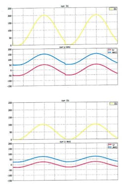
6. Simulation of hybrid transformer currents for 100A and 200A dc loads.
The upcoming Part 2 will continue the description of the Hybrid Switching converter.
NOTE: This converter is protected by a US Patent applied on March 28, 2011 and issued on January 6, 2016 as US 9,231,471 B2.
Companies interested to license the converter and partner with TESLAco in developing products are welcome to contact Dr. Slobodan Cuk at [email protected] or via Skype on slobodan.cuk.
ANNOUNCEMENT: 2nd MASTERCLASS - March 25-28, 2019 during Spring-break at UC Irvine following March 17-21, 2019 APEC conference in Anaheim (approx. 10 miles from UC Irvine)
The 2nd Masterclass will be a 4-day event divided as: CLASSIC POWER ELECTRONICS (first two days) and NEW POWER ELECTRONICS (following two days). The course will include detailed explanations of this Hybrid Switching converter and a number of others along with their simulation verifications using live demonstrations with .plecs and SIMPLIS simulation software.
Highlights of the 1st masterclass on Sept. 25-27, 2018 can be found at https://goo.gl/7LMmWG.
To register, visit https://teslaco.com/courses.

About the Author
Slobodan Cuk
Slobodan Ćuk is an author, inventor, business owner, electrical engineer, and professor of electrical engineering. The Ćuk switched-mode dc-dc converter is named for him. For over 20 years, until January 1, 2000, he was a full-time professor of electrical engineering at the California Institute of Technology (Caltech). In 1979, Slobodan founded TESLAco, which is currently located in Laguna Niguel, Calif. It had a charter to apply basic research results developed at Caltech to commercial, space, and military designs. This ultimately resulted in a family of hybrid Ćuk converters incorporated in the Orion spacecraft slated to land on Mars before 2030.
Other works produced at TESLAco include a multiple-output Ćuk converter incorporated in the F-22 Joint Strike Fighter plane; a heart defibrillator using a high-voltage step-up Ćuk converter, which was implanted in over 100,000 patients; and use of a similar converter by Ford Motor Company for HID lamps in their cars. More recently, the Ćuk-buck2 converter and PWM Resonant Ćuk converters have been patented and are available for license along with other patents. To date, over 50 patents have Ćuk's name on them. At the PCIM Europe 2011 conference, Leo Lorenz introduced Ćuk as a "father of power electronics." After five decades in the field, Cuk hopes to be remembered both as one of the founders of classical power electronics as well as a "father of modern power electronics."
Comment About the Article
To join the conversation, and become an exclusive member of Electronic Design, create an account today!

Leaders relevant to this article: