Microcontroller Converts Frequency to Voltage with High Resolution
Download this article in PDF format.
When you need to convert a measurement signal from the digital to the analog domain, this design is a suitable solution with only two chips. Frequency-to-voltage conversion has many applications in instrumentation circuits.
This design (Fig. 1) is based on the 14-pin PIC Microcontroller 16F753, which has an embedded 16-bit counter and a 9-bit digital-to-analog converter (DAC). The input frequency range for this design is within 0 to 50 KHz, and its output voltage is within the range of 0 to 4.99 V, with a resolution of 10 mV.
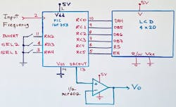
To achieve the conversion, the input frequency is separated into four scales, which are manually selected by the inputs SEL1 and SEL2 (Fig. 2).

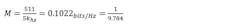
The DAC can deliver a maximum value of 4.99 V when its input code is 1FFh (511d), and 0.000V for a 000h input value. For the first scale, we get maximum and minimum values that are substituted in the following conversion equation:

Substituting those values, we get two equations:


Solving both equations we get:

And solving for M, we get:
Substituting both values in Equation 1, we get the offset value, and the result is Equation 3:

Now Equation 3 can be implemented in PIC basic code. But first, we need to measure the input frequency in 1.00 second intervals using TIMER1 as follows:
TMR1L = 0;                   Clearing TIMER1 registers
TMR1H = 0;
T1CON.0 = 1;                TIMER 1 Enabled
PAUSE 1000;                 for 1.00 Seconds
T1CON.0 = 0;                TIMER 1 Disabled
COUNTER.BYTE0 = TMR1L;      Storing both register in two bytes
COUNTER.BYTE1 = TMR1H;
Now we can apply Equation 3 as follows:
DIV = COUNTER *1000
DAC = DIV32 9784
DAC = DAC + offset;         freq offset = 0;
If we get 2,500 pulses in TIMER1, for example, we can get the DAC’s value by dividing the pulses read by the constant 9.784 that we found previously:

Then, converting this to the software code, we get:

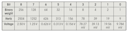
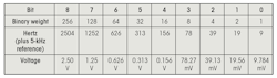
Now we can determine how many pulses are equivalent to each bit measured (Fig. 3).
For each scale, it’s necessary to obtain the constants by doing the same method used for Equations 1, 2, and 3. Thus, for the second scale (5-10 kHz), we get Equation 4:

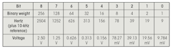
Then we determine how many pulses are equivalent to each bit (Fig. 4).
For the third scale (10-15 kHz), we get Equation 5:

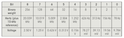
Then, we determine how many pulses are equivalent to each bit (Fig. 5).
For the fourth scale (10-50 kHz), we get Equation 6:

Then, finally, we determine how many pulses are equivalent to each bit in Figure 6.
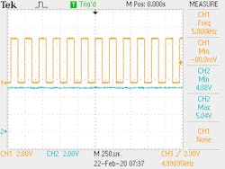
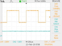
Figures 7 and 8 show two cases in the scope for different input frequencies with their respective voltage output. The code listing below shows the software code implemented in the PIC16F753.
Ricardo Jimenez holds a Master’s degree in electronics. He is the author of the book “The PIC Microcontroller Notebook, Vol 3,” ISBN: 978-1-7325906-1-8.
Gabriel Lee Álvarez is an Electronics Engineering student at ITM.
Software Code for the Frequency-to-Voltage Converter Based on the PIC16F753
'*  Name    : FREQ-TO-VOLTAGE.BAS
'*  Authors : Ricardo Jimenez and Gabriel Lee Alvarez
'*  Version : 1
;    PIC16F753
; Frequency to Voltage Converter
; 0hz - 5khz = 0v - 5 v;   1st Scale
;5khz - 10khz = 0 - 5v;   2nd Scale
;10khz - 15khz = 0 - 5v; 3rd Scale
;10khz - 50khz = 0 - 5v; 4th Scale
;pic16f753
; Oscillator and PORTS Configuration
OSCCON = $26; = $26; Clock set to 4 MHz
OSCTUNE = 0;
TRISA = %111110;     RA0 IS A OUTPUT, RA1:RA5 AS INPUTS
ANSELA = %000010; RA0:RA5 DIGIITALS
TRISC = %0000000;   RC0:RC2 AS INPUTS, RC3:RC5 AS  OUTPUTS
ANSELC = %000000;  RC0:RC5 AS DIGITALS
WPUA = %011100; RA2,RA3 PULL IS ENABLE
WPUC = %000000
DEFINE LCD_DREG PORTC ' PORTC is LCD data port
DEFINE LCD_DBIT 0 ' PORTC.0 is the data LSB
DEFINE LCD_RSREG PORTC ' RS is connected to PORTC.4
DEFINE LCD_RSBIT 4
DEFINE LCD_EREG PORTC ' E is connected to PORTC.5
DEFINE LCD_EBIT 5
DEFINE LCD_BITS 4 ' 4 data line are used
DEFINE LCD_LINES 2 ' It is a 2-line display
DEFINE LCD_COMMANDUS 1500 ' Use 1500uS command delay
DEFINE LCD_DATAUS 44 ' Use 44uS data delay
;---------SETTING UP LCD--------------------------------------------------------
LCDOUT $FE,$28;  $28 FUNCTION SET, 4 BITS
LCDOUT $FE,$10;  $10 SHIFT DISPLAY
LCDOUT $FE,$0C;  $0C DISPLAY ON
LCDOUT $FE,$06;  $06 ENTRY MODE SET
;------------TIMER CONFIG ----------
T1CON = %10000100;     $84 TIMER 1 DISABLE
;---HPWM SET to 250 Hz, when needed remove semicolons ---
;CCP1CON = %00001100; PWM mode selection and CCPx enabled
;PR2 = 79;     Value obtained from equation
;T2CON = %00000100;   enabling timer 2, PRESCALER 16
;CCP1CON.5 =0
;CCP1CON.4 =0
;CCPR1L = %000101000;

;ADC ENABLED
ADCON0 = %10000111; ENABLE ADC
ADCON1 = %00000000;FOSC/2

;-------- DAC  CONFIG ---------------------------------------
DAC1CON0 = %11100000;$E0, DAC ENABLED RIGHT JUSTIFIED
;---------DECLARING VARIABLES
COUNTER VAR WORD;            DECLARING COUNTING VARIABLES
;COUNTER.BYTE0 VAR TMR1L
;COUNTER.BYTE1
DAC VAR WORD;               VARIABLE TO BE USED BY DAC
SEL VAR BYTE;                    SCALE SELECTOR
HZ VAR BYTE[5];                DIGITS FOR HERTZ
DIV VAR WORD;
IN VAR BYTE;
VBE var word
OUT VAR BYTE;
I VAR WORD;
I2 VAR WORD;
ID VAR BYTE[3];
VIN VAR WORD;
VID VAR BYTE[4];
VED VAR BYTE[4];
VIN2 VAR WORD;
INVERT VAR PORTA.2; PIN FOR INVERTING DATA
x var byte;
VO VAR WORD[4];
OPTION_REG.7 = 0;
;--------PROGRAM STARTING ----------------

RPT:
;FIRST TEST, LET'S DO THE FIRST SCALE
;QUANTITY OF BITS IN THE DAC = 511, SO 5KHZ/511
;5KHZ/511 = 9.7843
;K=9.7843
FOR X = 0 TO 5; STARTING LOOPS
HZ[X] = "0";
VO[X] = "0";
VIN = 0;    CLEARING VARIABLES
IN = 0;
OUT = 0;
SEL = 0;
DAC = 0;
DIV = 0;
DAC = 0;
VID[X] = "0";
ID[X] = "0"
NEXT X;

LCDOUT $FE,$C0,"WAITING FOR SCALE "

OBTAIN_PULSES:;
LCDOUT $FE,$80,"HZ= ",HZ[4],HZ[3],HZ[2],HZ[1],HZ[0]," Vout= ",VO[2],".",VO[1],VO[0];

TMR1L = 0;  CLEARING REGISTERS IN TIMER1
TMR1H = 0;
T1CON.0 = 1;    TIMER 1 ENABLED
PAUSE 1000;
T1CON.0 = 0;    TIMER 1 DISABLED
COUNTER.BYTE0 = TMR1L;  STORING LOW BYTE REGISTERS
COUNTER.BYTE1 = TMR1H;  STORING HI-BYTE REGISTERS

FOR X = 0 TO 4;
IN = COUNTER DIG X;    GETTING DIGITS
LOOKUP IN,["0123456789"],OUT;  DECODING EACH DIGIT
HZ[X] = OUT;                   STORING DIGITS
NEXT X;

LCDOUT $FE,$80,"HZ= ",HZ[4],HZ[3],HZ[2],HZ[1],HZ[0]," Vout= ",VO[2],".",VO[1],VO[0];
;-----SELECTION------------
;FOR X= 0 TO 255
SEL = (PORTA & %011000)>>3; READING PORTA ANS SHIFT RIGHT BITS 3 SPACES
;SELECTING SCALE
IF SEL = %00 THEN GOSUB ESC1;     0-5KHZ
IF SEL = %01 THEN GOSUB ESC2;    10K-50K
IF SEL = %10 THEN GOSUB ESC3;    10KHZ-15KHZ
IF SEL = %11 THEN GOSUB ESC4;    5KHZ-10KHZ

IF INVERT  = 0 THEN DAC = 511-DAC;   INVERT DATA IF = 0
GOSUB V_DAC;
LCDOUT $FE,$80,"HZ= ",HZ[4],HZ[3],HZ[2],HZ[1],HZ[0]," Vout= ",VO[2],".",VO[1],VO[0];
GOSUB DAC_OUT;
GOTO OBTAIN_PULSES; GO TO LABEL OBTAIN_PULSES;
;------------------ FIRST SCALE  ------------------------------
ESC1:;                 0HZ A 5KHZ
;  getting Scale values
DIV = COUNTER *1000
DAC = DIV32 9784
IF (COUNTER >5000) THEN DAC = 0; ; EQUAL TO ZERO IF NOT IN RANGE
LCDOUT $FE,$C0,"0-5KHZ DAC= ",dec dac,"      "
RETURN;
;----------------------4th SCALE-------------------
ESC4:;                     10KHZ-50KHZ
DIV = COUNTER*100
DAC = DIV32 7827
DAC = DAC - 127;
IF (COUNTER >50000) OR (COUNTER <10000) THEN DAC = 0;EQUAL TO ZERO IF NOT IN RANGE
LCDOUT $FE,$C0,"10-50KHZ DAC= ",DEC DAC,"    "
RETURN;
;-----------------------3rd scale-----------------
ESC3:                      ; ESCALA 10KHZ - 15KHZ
DIV = COUNTER*1000
DAC = DIV32 9784
DAC = DAC - 1022;
IF (COUNTER >15000) OR (COUNTER <10000) THEN DAC = 0; DAC=0 IF NOT IN RANGE
LCDOUT $FE,$C0,"10-15KHZ DAC= ",DEC DAC,"      "
RETURN;
;------------------------------------------------------------------------------
ESC2:; SCALE 5KHZ - 10KHZ
; --------------getting the values for this Scale
IF (COUNTER >10000) OR (COUNTER <5000) THEN DAC = 0; DAC=0 IF NOT IN RANGE
LCDOUT $FE,$C0,"5-10KHZ DAC= ",DEC DAC,"       "
DIV = COUNTER*1000
DAC = DIV32 9784
DAC = DAC - 511;
IF (COUNTER >10000) OR (COUNTER <5000) THEN DAC = 0
LCDOUT $FE,$C0,"5-10KHZ DAC= ",DEC DAC ,"       "

RETURN;
;--VOLTAJE DAC---------
V_DAC:

DISABLE
VO[1]= DAC*976;        GETTING VOLTAGE FROM DAC
VO[3]= DIV32 100;      WITH RESPECT TO NUMBER
ENABLE
FOR X = 0 TO 2;
IN = VO[3] DIG (X+1);    FIND THE RESPECTIVE DIGITS
LOOKUP IN,["0123456789"],OUT;DECODING DIGITS
VO[X] = OUT;              STORE DIGITS
NEXT X;
RETURN;
;-------------------------------------------------------------------------------
DAC_OUT:
DAC1REFL = DAC.BYTE0;      modifying the DAC0 register
DAC1REFH = DAC.8;              modifying DAC0-bit 8
RETURN;
;------------------------------
END;
About the Author
Ricardo Jimenez
Ricardo Jimenez holds a master's degree in electronics from the Instituto Tecnologico de Mexicali.
Comment About the Article
To join the conversation, and become an exclusive member of Electronic Design, create an account today!

Leaders relevant to this article: