Microcontroller Sends Voltage and Frequency via Low-Cost Modules
Download this article in PDF format.
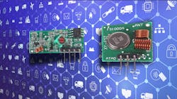
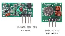
This project pairs a set of 8-bit microcontrollers with a 433-MHz industrial, scientific and medical (ISM) band transmitter/receiver. The FS1000A RF transmitter has a range of up to 200 m; the XY-MK-5V RF receiver operates at 5 V and uses only 4 mA (Fig. 1). These modules are readily available and used in projects with platforms like Arduinos.
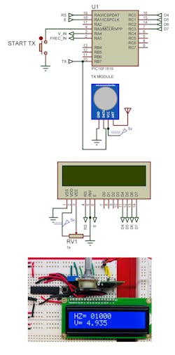
The projects uses Microchip PIC microcontrollers including the 16F1619 and 16F1614. These utilize the radio modules employing the on-chip EUSART (Enhanced Universal Synchronous/Asynchronous Receiver Transmitter) interfaces. On the transmitter side, we use the PIC’s analog and digital interfaces to read a voltage and a frequency source within the range of 0 to 4.99 V dc and 0 to 65.5 kHz, respectively.
The logic diagram for the transmitter (Fig. 2) includes an LCD display to provide feedback. Listing 1 (see at end of article) has the code for the 16F1619.
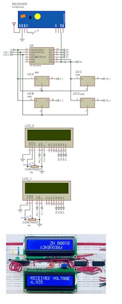
The receiver side (Fig. 3) also includes a pair of LCD displays. The displays aren’t needed in an application, but they’re handy for debugging. Listing 2 (see at end of article) has the code for the 16F1614.
Serial Communication
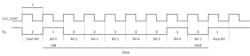
First, we will touch on the serial communication support that’s tied to the wireless modules. To establish communication, it’s necessary to have a starting bit for a period of time to alert the receiver that a data package is about to be transmitted. This forces the receiver clock to start synchronization with a 0 bit. Then each bit is sent individually, starting with the LSB bit through the MSB bit (see table below). Each bit has the same period. Once all bits are transmitted, it must wait for the Stop bit to indicate end of transmission. This is achieved with a High logic, where the communication ends.
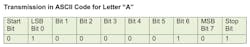
To transmit the alphanumeric character “A,” whose ASCII code is 0b01000001 (Fig. 4), the bits are organized as shown in the table. Each bit has a period determined by the transmission speed (baud rate), which can vary from 115.2 kb/s to 200 bits/s.
The time for each bit is given by:

To transmit a voltage, we will read it using the 10-bit analog-to-digital converter (ADC), which by default has its reference voltage connected to 5 V. This defines the ADC resolution:

To perform the binary to decimal conversion, we use this code:
VINBCD = VIN*4887 ; multiplying by RESlsb = 4.8887VR = div32 1000 ; perform 16-bit division
where VIN is the binary voltage read by the ADC, and VR is the voltage result.
TIMER1 takes care of reading frequencies and is configured to read the number of pulses in one second. After that, the PIC transmits and receives those readings. With the data ready, the instruction HSEROUT sends the serial data. The code is always waiting to be activated by the user. Once activated, it sends a control variable to the receiving unit with the instruction HSEROUT, which is sent at a speed of 2400 bits/s. This variable indicates that data transmission is starting:
HSEROUT ["BZ0",10]; SEND ACTIVATION INSTRUCTIONFor the transmitter code, it’s necessary to read a voltage and frequency with the microcontroller’s ADC and TIMER1, respectively. The maximum frequency is:

Then the code proceeds to obtain each decimal digit with the command DIG, and each digit is sent at 2400 bits/s with the serial data with the instruction Hserout. Two digits in ASCII code are inserted at the beginning of each data package, so that the receive identifies which data is receiving.
HSEROUT ["BZ",DEC A,10];HSEROUT ["AZ",VD[3],VD[2],VD[1],VD[0],10]; send serial dataHSEROUT ["CZ",H[4],H[3],H[2],H[1],H[0],10];
When the receiver gets the data “BZ,” it represents the activity control in the serial port. The data package AZ represents the Voltage, while the data package CZ represents Frequency.
When the Micro receives the stop instruction with the pushbutton, it transmits a “1” in the control data package, indicating end of transmission.
The receiver waits for the control variable BZ with the instructions HSERIN and WAIT, which waits specifically for the data “BZ”. Because that RF data transmission has external noise, after receiving the data BZ, the next data is stored in a variable to manipulate as follows:
HSERIN 10,MAIN1,[WAIT("BZ"), STR A\1]; wait one second to receive instructionWhen the second micro receives the control variable, it starts the data input where the instructions HSERIN wait for ASCII codes in each package that’s transmitted. If it doesn’t receive any data, the code jumps to the next instruction as follows:
HSERIN 10,JUMP1,[WAIT ("BZ"), STR A\1]JUMP1: HSERIN 100,JUMP2,[WAIT ("AZ"), STR VD\4]JUMP2: HSERIN 10,HERE, [WAIT ("CZ"), STR H\5]
When the data is received, it’s transferred to two LCD displays. By using a CMOS switch
About the Author
Ricardo Jimenez
Ricardo Jimenez holds a master's degree in electronics from the Instituto Tecnologico de Mexicali.
Comment About the Article
To join the conversation, and become an exclusive member of Electronic Design, create an account today!

Leaders relevant to this article: