Measure RTD Sensors without a Precision Current Source
Download this article in PDF format.
Traditionally, resistance-temperature-detector (RTD) sensor resistance is measured by applying a precision current source and measuring the developed voltage. This approach usually requires a precision voltage reference to create the current source, followed by a high-quality analog-to-digital converter (ADC) to measure the voltage.
This isn’t difficult to achieve at room temperature, but when you consider that the temperature of your measuring system can be in the range of −40 to +55°C, the task becomes more daunting.
A brute-force approach to this problem would be to use an expensive temperature-stable voltage reference, ADC, and other components combined with software calibration to compensate for the temperature drift of parameters. This approach is complex and will fail to achieve the high precision that borderlines the sensor accuracy.
A better approach was discovered using 5 ppm/°C ultra-stable resistors with 0.1% accuracy as a reference for RTD measurements. This approach requires two onboard ultra-stable resistors for calibration (1k and 2k) to achieve high RTD precision. Those resistors are used to calibrate the RTD reading and compensate for temperature-drift errors.
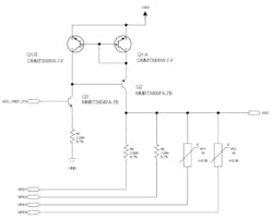
The design uses the Q1-Q3 transistors in combination with the R1 resistor to form a constant-current source that sources about 1 mA using a 2.5-V ADC voltage reference (see figure). Calibration resistors R4 and R5 along with the RT1 and RT2 RTD sensors can sink this current when the corresponding GPIO pin is driven low. When not used, the GPIO pins are tri-stated. The voltage is measured at the ADC output.
For calibration, we will need to read two resistors and calculate the constant-current source value and combined errors, which we call VOffset. The calibrated Icc and VOffset values are used to convert RTD temperature readings.
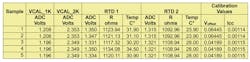
The calibration results (see table above) are applied using following formula:

where:
- RRTD is the measured RTD resistance.
- VADC is the ADC voltage reading.
- ICC is a somewhat constant-current source.
- VOffset is the voltage offset of cumulative errors. Note that this variable is a combination of multiple error voltage sources. Therefore, it might be beneficial (though not necessary) to split into its components to get better precision.
To calculate VOffset and ICC, we need to make a few assumptions to derive the formula below:
- First assumption: Calibration resistors are ideal and have 1,000- and 2,000-Ω values, respectively.
- Second assumption: The ICC current source is stable for the duration of measurements.
- Third assumption: ADC conversion results are perfect.
Following those assumptions, we can write that:
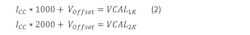
In Equation 2, VCAL1K and VCAL2K represent voltages developed on calibration resistors when ICC current is applied.
By solving those equations for ICC and VOffset, we get the following equations:


Experimental Setup Measurements
The experimental setup has two calibration resistors and two RTDs mounted on different locations. We used an ADC with 10-bit resolution and surface-mount RTDs rated 1k at room temperature. Notice how the calibration values change when board temperature changes between sample 2 and 3 in the above table.
To gather the data, the software followed these steps:
1. Read ADC voltage levels on calibration resistors and RTDs.
2. Calculate Voffset using Equation 3.
3. Calculate ICC with Equation 4.
4. Determine RTD resistance utilizing Equation 1.
5. Convert RTD resistance values to temperature with the table lookup and piecewise interpolation.
Vardan Antonyan is Senior Electrical Engineer at Glenair Inc.
About the Author
Vardan Antonyan
Senior Hardware Engineer
Vardan Antonyan is a senior hardware engineer at Aitech Defense Systems Inc. (www.rugged.com), Chatsworth, Calif., with over 15 years of experience. He also has a patent. He can be reached at [email protected].
Comment About the Article
To join the conversation, and become an exclusive member of Electronic Design, create an account today!

Leaders relevant to this article: