Microcontroller Efficiently Measures Frequency and Period
Download this article in PDF format.
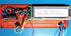
When you need to take accurate timing measurements in hardware without overloading a microcontroller, the signal measurement timer module (SMT) in the Microchip 16F1619 PIC microcontroller is perfectly suitable for this application. The SMT module captures features of a signal such as Period and Frequency, among others. This design measures input frequency signals within the range of 8 Hz to 10 MHz, and Period signals within the range of 0.1 µs to 125 ms. Figure 1 shows the prototype circuit.
The module’s operation consists of reading data of a 24-bit timer/counter and transferring it to three registers called TMR, CPR, and PR. The SMT can perform a variety of measurements such as Gated Timer, Period and Duty Cycle Acquisition, High and Low Measurement, Windowed Measurement, Gated Window measurement, Time of Flight, Capture, Counter, Gated Counter, and Windowed Counter.
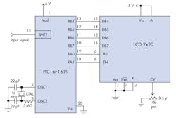
In this application, we use the SMT module in Period and Duty Cycle acquisition mode. Figure 2 shows the electronic schematic for this design.
The Period and Duty Cycle mode has two modes of operation. The first works as single acquisition, which can take the timer/counter contents. You can configure it to the rising edge of the signal to start reading, or go to acquisition and set the falling edge as an interrupt. The second mode can read and save the counter value settings, the GO and Interrupt acquisition, by just configuring the SMTxGO register. In this design, we’re using the second mode. To understand how this counter and its registers work, we need to check the timing diagram.
According to the datasheet’s timing diagram, we have a delay before starting the counter for synchronization purposes; the time depends on the internal or external clock. We set in software a 50-ms delay after starting an acquisition. The setting code for the SMT MODULE as a Period and Duty Cycle acquisition is:
SMT1CLK = %00000001; SMT Clock Selection Register (we select Fosc/4)
SMT1SIG = 0; Signal Input Select Register (we can use almost every pin as an SMT input; in this case, SMTSIG1 is selected by default)
Those registers are for initialization only, we have to select the clock and its input port, even if they’re selected on the SMT register. There are two control registers for the SMT module. We need to set both to take a measurement. The operation of those bits is described as follows (the STxCON is the control register):
SMT1CON0:
BIT 7: Enables the SMT module; if this bit is set to 0, the entire SMT is disabled.
BIT 6: Unimplemented.
BIT 5: Stops the counter; it’s used for interrupt options.
BIT 4: Window input polarity for measurements at rising or falling edge.
BIT 3: Input signal polarity; enables measurements at rising or falling edge.
BIT 2: Clock input polarity; increments counter at rising or falling edge.
BIT 1 & 0: SMT module prescaler
SMT1CON1:
BIT 7: Starts to get data from the counter clock; if disabled, it doesn’t count.
BIT 6: This bit lets us choose between two methods of operation: single measurement or take and repeat. For the single measurement, you have to select the polarity options to take measurements at the rising edge or stop at the falling edge.
BITS 5 & 4: Unimplemented.
BITS 3 to 0: The operational mode is assigned by setting those bits.
As you can see in the Code Listing below, we’re using a 20X2 LCD display to show period measurements. These measurements can’t be read directly, because the value in the counter is a Frequency. Thus, it must be converted to Period. Then we set the clock to 16 MHz with an external crystal, and in the SMT module we set the Prescaler value to 4, and the period scale to 4. We have an SMT clock of 1 MHz; to determine the time we get:

Thus, we have 1us for each clock pulse, that means if we have a period of 1ms we should have 1000 pulses with a constant period. And to get the frequency we use Equation 2:

To determine the quantity of pulses, we need to divide SMTF osc by the Frequency:

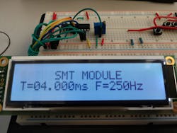
As you can see, those values are floating or of the double variable type. We can’t use decimal numbers in the PBP3 compiler, so we need to look for an equation to solve this. In this case, we read 250 Hz in the SMT module with a 1-MHz internal clock. That means with Equation 1, the period will be 4000 pulses—here, we know that 1 µs equals to 1 pulse, which is equivalent to 4 ms. If the clock is set to 4 MHz, we get 16000 pulses, which is a 16-bit number.
For period measurements each pulse is 250 µs, which means we have to multiply the value of the SMT pulses data by a constant. Then we would get 400000. This isn’t a 16-bit number, so we need a multiplying factor. The number near to a real binary number is 25—because of the 250 µs in each pulse, this number will be our multiplying factor, which leads to Equation 4:

By using the DIV32 command in PBP3, we can take all 31 bits from the internal result on an internal variable of the multiply function that operates as a 16- × 16-bit and divide by 100. Then we get Equation 5:

Now we have a valid 16-bit number that represents the reading in milliseconds. That means, we have digit 4 and digit 3 as integer numbers and the other for floating values. However, this is valid specifically for this configuration.
Now we must separate the different values of period into scales. We do this in four scales. For example, in the first scale, we configure the SMT clock using the Fosc/4 and the prescaler to 1:8; then we have SMTFosc equal to 500,000 Hz. If we use Equation 1, we would get each pulse equal to 2 µs. Due to the maximum 16-bit pulses of period measurement, we must set a scale value, in this case, from 8 to 100 Hz.
To test it, we apply a 50-Hz input signal from an external pulse-width modulation (PWM) into the read pin. Then, via Equations 1 and 3, we get 10000 pulses into the data register in the SMT module. To know the period value, we multiply the pulses by 2 µs. Therefore, we look for our multiply factor; in this case, the nearest real number for 2 µs is 2.
Now we have the Period value:

And using the Div32 Function:

Now that we have a regular 16-bit number, we separate each digit and multiply it by its real value. This number gives the Period value in milliseconds. Subsequently, we need to calculate the Frequency based on the Period measurement. We take the value from the data register—we got 10000 pulses—and then, using Equation 3, we solve for Frequency:

We proceed to divide by 10 to take a lower number, 1000, and divide by the nearest 16-bit number factor related to the SMTFosc, which in this case is 50000:

The result is 50 Hz. We can repeat this process for each scale based on its SMTFosc and Period Factor.
The complete software code is presented in the Code Listing below.
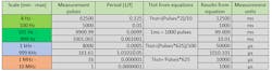
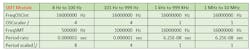
Table 1 shows the SMT module configuration for each scale. Table 2 shows a summary of input frequencies with their respective results.
Ricardo Jimenez holds a Master’s degree in Electronics Engineering. He is the author of several Lab Notebooks using PIC Microcontrollers.
Kevin A. Martinez is pursuing his Electronics Engineering degree at ITM.
Code Listing: Software Code for Period and Frequency Measurements
'*  Name    : SMT Module
'*  Authors  : Ricardo Jimenez and Kevin Adrian Martinez
'*  Date    :     7/06/2020
'*  Version : 1.0
'*  Notes   :  PBP3.1 Compiler
'*          :
;--- PIC16F1619 CONFIGURATION
#CONFIG;                                                  Starting Configuration bit setting.
    __config _CONFIG1,  _FOSC_HS    ;  setting FOSC HS mode on.
    #endconfig ;                                         end of configuration mode.

TRISA = %00100000;  RA5 set as input
TRISB = 0;                     PORTB set as output
TRISC = %00000010;  RB1 set as input
LATA = 0: LATB = 0: LATC = 0;   Clearing all Latches
ANSELA = 0: ANSELB = 0: ANSELC = 0; All inputs set to digital
OSCCON = %01111000;     16.000 MHZ Xtal
OSCSTAT = %00010001;
DEFINE OSC 16;
x var word: CPRL var WORD: CPRH VAR WORD: CPRU var word: D0 VAR BYTE: D1 VAR BYTE: D2 VAR BYTE: D3 VAR BYTE: D4 VAR BYTE;
err var byte: T var word: A var word: b var word:c var word:Ttot var word: Tvalue var word;
CTOT VAR WORD:Period var word:fqz var word: C1 VAR WORD:C2 VAR WORD:C3 VAR WORD:C4 VAR WORD: C0 var word ;
OPTION_REG.7=0; PORTB PULL UP resistors ENABLED
DEFINE adc_bits 10;
define adc_clock 3;
define adc_sampleUs 50;

;------ENABLES 250HZ PWM USING THE EQUATION------------------
;RC5PPS = %00001100;  SETTING CCP1 AS AN OUTPUT AND ENABLE IT
;CCP1CON = %10001100; PWM mode selection and CCPx enabled
;PR2 = 249;     Value obtained from equation
;T2CON = %11000000;   enabling timer 2
;CCPTMRS = %11111100; CCP1 IS BASED OFF TIMER 2
;CCPR1L = %11110100;  VALUE obtained from equation
;CCPR1H =%00000001;    VALUE obtained from equation
;---------LCD CONFIGURATION---------------------------------

DEFINE LCD_DREG PORTB;
DEFINE LCD_DBIT 4;
DEFINE LCD_RSREG PORTA;
DEFINE LCD_RSBIT 0;
DEFINE LCD_EREG PORTA;
DEFINE LCD_EBIT 1;
DEFINE LCD_BITS 4;
DEFINE LCD_LINES 2;
DEFINE LCD_COMMANDUS 1500;
DEFINE LCD_DATAUS 45;

;---------SETTING UP LCD-----------------------------------
LCDOUT $FE,$28;  $28 FUNCTION SET, 4 BITS
LCDOUT $FE,$10;  $10 SHIFT DISPLAY
LCDOUT $FE,$0C;  $0C DISPLAY ON
LCDOUT $FE,$06;  $06 ENTRY MODE SET
;-------------------------------------------------------------------
;setting STM module for period measurement
SMT2SIG = 0;   SIGNAL INPUT SELECT REGISTER, We use SMTSIG1 as input by default
;--------MAIN-----
;clearing variables
               D0 = 0;
D1 = 0;
D2 = 0;
D3 = 0;
D4 = 0;
fqz = 0;
T = 0
;MAIN LOOP
RPT:
gosub FREQAUTO;     this is the label where we calculate frequency.
goto RPT;
;-------------------------------------------------------------------------------

SMTRead:
SMT2CON1 = %11000010;     BIT7 as '1' for data acquisition, bit 6 to repeat acquisition,
                                             ;      bits 0-4 for SMT operation mode, period and duty cycle
STAY: IF SMT2STAT.0==1 THEN GOTO STAY;
pause 50;                                   this pause is for SMT sync purposes
  CPRL= SMT2CPRL;                  data is captured for first 8 bits
  CPRH= SMT2CPRH*256;       data is captured for the next 8 bits
  CPRU= SMT2CPRU;               data is captured for the next 8 bits
    Period= CPRL+CPRH;
    D0= Period DIG 0;
    D1= Period DIG 1;
    D2= Period DIG 2;
    D3= Period DIG 3;
    D4= Period DIG 4;
    SMT2CON1.7 = 0;   BIT7 as '0' for interrupt data acquisition.
return

LCDSHOWHZ:
LCDOUT $FE,$80,"     SMT MODULE    ";  $80 FIRST LINE LOCATION
LCDOUT $FE,$C0,"T= ",DEC Ttot,"mS F=",dec fqz,"Hz";  $C0 SECOND LINE LOCATION
pause 1000;
goto RPT;
RETURN;
LCDSHOWHZ2:
LCDOUT $FE,$80,"     SMT MODULE    ";  $80 FIRST LINE LOCATION
LCDOUT $FE,$C0,"T=",DEC D4, DEC D3,".",DEC D2,DEC D1,"ms F=",dec fqz,"Hz";  $C0 SECOND LINE LOCATION
pause 1000;
goto RPT;
RETURN;
LCDSHOWKHZ:
LCDOUT $FE,$80,"     SMT MODULE    ";  $80 FIRST LINE LOCATION
LCDOUT $FE,$C0,"T=",DEC Ttot,"ms F=",dec fqz,"KHz";  $C0 SECOND LINE LOCATION
pause 1000;
goto RPT;
RETURN;

LCDSHOWMHZ:
LCDOUT $FE,$80,"     SMT MODULE    ";  $80 FIRST LINE LOCATION
LCDOUT $FE,$C0,"T=",DEC Ttot,"uS", "F=",dec fqz,"MHz";  $C0 SECOND LINE LOCATION
pause 1000;
goto RPT;
RETURN;

LCDSHOWMHZ2:
LCDOUT $FE,$80,"     SMT MODULE    ";  $80 FIRST LINE LOCATION
LCDOUT $FE,$C0,"T=",DEC Ttot,"nS", "F=",dec fqz,"MHz";  $C0 SECOND LINE LOCATION
pause 1000;
goto RPT;
RETURN;

FREQAUTO: ; 8Hz TO 100Hz
  SMT2CLK = %00000001;        SMT CLOCK SELECTION REGISTER, set to Fosc/4
  SMT2CON0 = %10000011;   SMT CONTROL REGISTER,  bit7 set as '1' enables the SMT function  and prescaler 1:8
  gosub SMTRead;
  T = (D4*10000) + (D3*1000) + (D2*100) + (D1*10) + D0
  if T < 5000 then gosub FREQAUTO2
  A = Period * 2
  Tvalue = div32 10
  C2= Tvalue DIG 2;
  C3= Tvalue DIG 3;
  C4= Tvalue DIG 4;
  Ttot = (C4*10000) + (C3*1000) + (C2*100)
  A = T/10;
  fqz = 50000/A
  if CPRU != 0 then
        gosub errSHOW;
  endif
  gosub LCDSHOWHZ;
return;

FREQAUTO2: ;    101--Hz TO 999Hz
  pause 50
  SMT2CLK = %00000001; SMT CLOCK SELECTION REGISTER,  set to Fosc/4
  SMT2CON0 = %10000010; SMT CONTROL REGISTER, the bit7 set as '1' enable the SMT function and prescaler 1:4
  gosub SMTRead
  T = (D4*10000) + (D3*1000) + (D2*100) + (D1*10) + D0
  if T < 1000 then gosub FREQAUTO3
  b=10000;
  c=100;
  A = b*c;
  fqz = DIV32 T
  if CPRU != 0 then
        gosub errSHOW;
  endif
  gosub LCDSHOWHZ2;
return;

FREQAUTO3: ;                  1-KHz TO 999-K Hz
  SMT2CLK = 0;                 SMT CLOCK SELECTION REGISTER, we are using the Fosc
  SMT2CON0 = %10000000; SMT CONTROL REGISTER, the bit7 set as '1' enable the SMT function and prescaler 1:1
  gosub SMTRead
  T=15984;
  T = (D4*10000) + (D3*1000) + (D2*100) + (D1*10) + D0
  if T < 161 then gosub FREQAUTO4
  A = Period * 625 ; 1/16Mhz
  Tvalue = div32 100; Period value in uS
  C2= Tvalue DIG 2;
  C3= Tvalue DIG 3;
  C4= Tvalue DIG 4;
  Ttot = (C4*10000) + (C3*1000) + (C2*100)
  b=16000;
  c=10
  A = b*c;
  fqz = DIV32 T;
  if CPRU != 0 then
        gosub errSHOW;
  endif
  gosub LCDSHOWKHZ
return;

FREQAUTO4: ;       1.000-MHz TO 10.000-MHz
  SMT2CLK = 0; SMT CLOCK SELECTION REGISTER, we are using the Fosc
  SMT2CON0 = %10000000; SMT CONTROL REGISTER, the bit7 set as '1' enable the SMT functionv and prescaler 1:1
  gosub SMTRead
  T = (D4*10000) + (D3*1000) + (D2*100) + (D1*10) + D0
  if T < 1 then gosub errSHOW ;
  Tvalue = Period * 625;    Period value in uS
  C1= Tvalue dig 1;
  C2= Tvalue DIG 2;
  C3= Tvalue DIG 3;
  C4= Tvalue DIG 4;
  Ttot = (C4*10000) + (C3*1000) + (C2*100) + (C1 * 10)
  fqz = 160/T;
  if CPRU != 0 then
        gosub errSHOW;
  endif
  gosub LCDSHOWMHZ2;
return;

errSHOW:
LCDOUT $FE,$80,"     SMT MODULE    ";  $80 FIRST LINE LOCATION
LCDOUT $FE,$C0,"  OUT OF RANGE  ";  $C0 SECOND LINE LOCATION
pause 4000;
RETURN;
End
About the Author
Ricardo Jimenez
Ricardo Jimenez holds a master's degree in electronics from the Instituto Tecnologico de Mexicali.
Comment About the Article
To join the conversation, and become an exclusive member of Electronic Design, create an account today!

Leaders relevant to this article: