Microcontroller Delivers High-Precision Frequencies
Members can download this article in PDF format.
What you'll learn:
- How to set up an PIC microcontroller to deliver high-precision frequencies from 1 Hz to 4 MHz.
- Examples of the frequencies delivered by this microcontroller design.
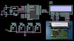
In timing applications, a time-base generator is a crucial component for achieving accurate readings. In the past, classic time-base generators from the MM5369 family were used to generate accurate time-base signals. In this design (Fig. 1), the PIC microcontroller 16F1619 is used to generate high-precision frequencies within the range of 1 Hz to 4 MHz.
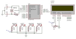
The microcontroller’s pulse-width-modulation (PWM) and capture, compare, and PWM (CCP) modules deliver a PWM signal with a specific duty cycle, period, and resolutions that are configured by registers PRx, TxCON, CCPRxH, CCPRxL, and CCPxCON. The PWM module has a 10-bit resolution output and uses Timer2 and PR2 registers to set the signal’s period. The CCPRxL and CCPRxH registers configure the duty cycle. Therefore, if we keep the duty cycle at 50%, we can make an oscillator, and by controlling the period set register, we’re able to generate a desired frequency signal.
Knowing this, we need to calculate the PWM pulse width, duty cycle, and period, using the equations below.
Pulse-Width Equation
The pulse width is determined by the period of internal oscillator, DCH and DCL registers, and the Timer2 Prescale value:
(Equation 1)

Pulse Width = CCPRxL:CCPxCON * Tosc * (TMRx Prescalar value)
where:
(Equation 2)

Tosc = 1/Fosc
PWM-Period Equation
The PWM period is specified by register PR2 of TIMER2. This period can be calculated using Equation 3:
(Equation 3)

PWM Period = [(PRx) + 1] * 4 * Tosc * (TMRx Prescalar value)
where:
(Equation 4)

PWM Period: 1/Output Frequency

and PRx is a Register of Timer X.
Duty-Cycle Ratio Equation
The PWM duty cycle is specified by writing a 10-bit value to multiple registers CCPR1L, and DC1B <1:0> bits of the CCP1CON register:
(Equation 5)

Duty Cycle Ratio - (CCPRxH:CCPRxL)/[4(PRx+1)]
PWM Resolution
The resolution determines the number of available duty cycles for a given period:
(Equation 6)

Resolution = (log[4(PRx+1)])/log(2) bits
At this point, we know all of the equations that are needed, and how registers can be configured.
Now, if we want a 250-Hz signal oscillator, for example, we can use Equation 4 to get:
(Equation 7)

PWM Period: 1/Out Frequency = 1/250Hz = 0.004s
We need a period equal to 4 ms, so by using Equation 3, we can get the PR2 value based on the TMR2 prescale value:
(Equation 8)

PWM Period = [(PPRx) + 1] * 4 * Tosc * (TMRx Prescaler value)
Solving for PRx we get Equation 9:
(Equation 9)

PR2 = ([PWM Period]/[4 & Tosc * (TMRx Prescaler value)]) - 1
setting the internal clock to 4 MHz:
(Equation 10)

Tosc = 1/Fosc = 1/4 MHz = 2.5*10-7s
And setting the TMR2 prescale to 1:16, we can substitute these values into Equation 9 to get PR2:
 (Equation 11)

PR2 = (0.004s/[4*2.5*10-7s*(1:16 Prescaler value)]-1 = 250-1 = 249
Then for 250 Hz, we need to set PR2 to a 249 decimal value. Now that we have a PR2 value for this frequency, we have to set registers CCPRxL and CCPRxH for a 50% duty cycle. Then, using Equation 5, we get:
(Equation 12)

Duty Cycle Ratio= (CCPRxH:CCPRxL)/[4(PRx+1)]
Solving for CCPRxH and CCPRxL, we get:
(Equation 13)

CCPRxH:CCPRxL = Duty Cycle Ratio * 4(PRx +1) = 50% * 4(249 + 1) = 500
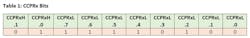
The result is 500, which in binary code is 0111110100. Thus, we have the 10 bits for CCPRx, and we set FMT = 0, for a right justified alignment (Table 1).
Now, to convert this to PBP3 code, we need to set all registers as shown below. In this case, we need to generate a 250-Hz signal:
/For 250Hz/
RC3PPS  = %00001101    ; setting CCP1 as an output and enabling PPS.
CCP1CON = %10001100    ; selecting PWM mode and CCP1 enabled.
PR2     = %11111001    ; setting PR2 = 249
T2CON   = %11000000    ; Enabling TMR2 and Prescale to 1:16.
CCPR1L  = %11110100    ; value obtained from equation
CCPR1H  = %00000001    ; value obtained from equation
/end/
RC3 is the CCP1 output—that pin is going to generate the oscillator output.
Considering a microcontroller as an efficient controlled oscillator, we have to set the frequency ranges. Therefore, if we manipulate PR2 from 0 to 255, we get 256 different frequencies values for each prescale. Knowing this, we can take PR2 as our input variable and, at the same time, set it as a constant with prescaler and duty-cycle values. Then the microcontroller can solve the PWM equation to determine the output frequency.
For example, if we get a prescale set of 1:128 and the Internal oscillator is 4 MHz, we can get a Constant Factor to solve Equation 9 for that frequency.
Thus, solving for Fout we get:
(Equation 14)

Fout = 1/[4*Tosc*(TMRx Prescaler value)*(PR2 + 1)]
Then if we separate all the constants values, we get 7812.5 as Constant Factor:
(Equation 15)

Fout = 1/[PR2 + 1] * 1/[4*Tosc*(TMRx Prescaler value)] = 1/(PR2 + 1) * 7812.5
The nearest integer number for this factor is 78125, but it’s greater than a 16-bit number. Therefore, we need to multiply two numbers to get 78125 to take advantage of the 32 bits as an internal result; 15625 x 50 gives this number.
Now solving for Fout, each frequency value that we can reach will depend on the PR2 value. Thus, the minimum value for PR2 = 255 is 30.52 Hz, and for PR2 = 0 it’s 7.81 kHz. So, if we apply all of this over again, but with a different prescaler value, we can take other range of reachable frequencies.
The last step is to set the CCP register, which we set at 50% of the duty cycle using Equation 5:
(Equation 16)

(CCPRxH:CCPRxL) = 2 * (PR2 + 1)
If we save this as a word type variable, we get all 16 bits. To separate them, we can use a byte command to extract the 8 bits and save them on CCPRxL and CCPRxH.
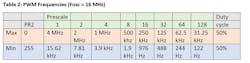
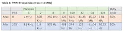
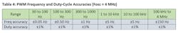
An example of the frequencies this design can deliver is shown in Tables 2, 3, and 4. In Table 2, the microcontroller uses the internal oscillator at 16 MHz. Table 3 shows a frequency range within 30 Hz and 4 MHz. And Table 4 shows the frequency and duty-cycle accuracies.
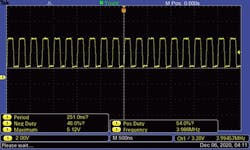
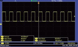
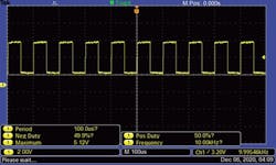
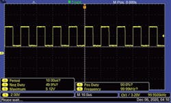
Figures 2, 3, 4, and 5 show the scope images for four different delivered frequencies by the PIC microcontroller.
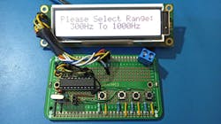
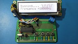
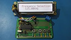
Figures 6, 7, and 8 show the actual assembled PC circuit with three different freqeucy selection cases.
The listing below shows the code using the PBP3 compiler from melabs.com.
Code for the Oscillator
'*  Name    : Controlled Oscillator.BAS
'*  Authors  : Ricardo Jimenez and Kevin A. Martinez
'*  Notice  :   Compiled with PBP3 version 3.1 from melabs.com
'*  Date    :   1/04/2021
'*  Notes   :   PIC16F1619 with external 4.000 MHz XTAL
;    on interrupt goto SET;   IF INTERRUPT GO TO LABEL SEL
 #CONFIG; FUSSES
    __config _CONFIG1,  _FOSC_HS & _PWRTE_ON & _MCLRE_OFF & _CP_OFF & _BOREN_ON & _CLKOUTEN_OFF
    __config _CONFIG2,  _WRT_OFF & _PPS1WAY_OFF & _ZCD_OFF & _PLLEN_OFF & _STVREN_ON & _BORV_LO & _LVP_OFF
    __config _CONFIG3,  _WDTCPS_WDTCPS4 & _WDTE_ON & _WDTCWS_WDTCWS100 & _WDTCCS_LFINTOSC
  #ENDCONFIG
;#CONFIG
;    __config _CONFIG1,  _FOSC_HS
 ;   #endconfig
;SETTING INTERNAL OSCILLATOR
OSCCON =  %01101000;    16MHZ
;OSCSTAT = %00010001;  INTERNAL CLOCK
OSCTUNE = 0;
;SETTING PORTS
;--PORTB--
TRISB = 0; ALL AS outputs
ANSELB = 0; ALL AS DIGITAL
WPUB = 0; PULL UPS DISABLED
;--PORTC--
TRISC = %00011000; RC3 and RC4 as inputs
ANSELC = %00000000; ALL AS DIGITAL
WPUC = 0; PULL UPS DISABLED
;--PORTA--
TRISA = %00101100; RA5,RA3 and RA2 as inputs
ANSELA = 0;   ALL DIGITAL
WPUA = 0;     PULL-UP resistors disabled
;--LCD CONFIGURATION ----------------------
define OSC 16
DEFINE LCD_DREG PORTB ' PORTC is LCD data port
DEFINE LCD_DBIT 4 ' PORTB.4 is the data LSB
DEFINE LCD_RSREG PORTA ' RS is connected to PORTA.0
DEFINE LCD_RSBIT 0
DEFINE LCD_EREG PORTA ' E is connected to PORTA.1
DEFINE LCD_EBIT 1
DEFINE LCD_BITS 4 ' 4  data line
DEFINE LCD_LINES 2 '  2-line display
DEFINE LCD_COMMANDUS 1500 ' Use 1500uS command delay
DEFINE LCD_DATAUS 44 ' Use 44uS data delay
;---------SETTING UP LCD-------------------------------------------------------

LCDOUT $FE,$28;  $28 FUNCTION SET, 4 BITS
LCDOUT $FE,$10;  $10 SHIFT DISPLAY
LCDOUT $FE,$0C;  $0C DISPLAY ON
LCDOUT $FE,$06;  $06 ENTRY MODE SET
;------------------------------------------------------------------------------
f var word: fout var word: prx var word: pr var word: CCP var word: x var word
C var word: A var byte: F32b var word: i var byte: FD var byte[4]: fent var word
k var byte
;--------------------INTERRUPT CONFIGURATION-------------------------

;INTCON = %11001000;ENABLE INTERRUPT
;IOCAN = %001000; RA3 INTERRUPT
;;------------------ADC CONFIG-----------------------------------
ADCON0 = %00001101;ADC ENABLED
ADCON1 = %10000000; RIGHT JUSTIFIED
;---------- ----------------------------------------------------
;-----Initializing variables----------
f=255;
A=1;
;-----------------Creating Special Characters------------------
LCDOUT $FE,$40,$01,$01,$01,$01,$01,$01,$01,$1F 'L symbol
pause 50
LCDOUT $FE,$48,$1F,$01,$01,$01,$01,$01,$01,$01 'L symbol
pause 50
LCDOUT $FE,$50,$00,$00,$00,$00,$00,$00,$00,$1F 'L symbol
pause 50
LCDOUT $FE,$58,$1F,$00,$00,$00,$00,$00,$00,$00 'L symbol
pause 50
;-----------------initializing PWM-----------------------------
RC5PPS=%00001100;       SETTING CCP1 AS AN OUTPUT AND ENABLE IT
CCP1CON=%00001100;      PWM mode selection and CCPx disabled
CCPTMRS=%11110100;      CCP1 AND CCP2 ARE BASED OFF TIMER 2
PAUSE 50;               pause to save the PWM configuration
;---------------------------first start lcd show ------------------
 lcdout $fe,$80," MICRO-CONTROLLED      "    ; MESSAGES
 lcdout $fe,$c0," OSCILLATOR ",0,1,0,1,2;
pause 1000;
WHILE(1)        ;waiting interrupt
 if PORTA.3=0 then
    LCDOUT $fe,1;
    goto SETRange
 endif
 pause 15 ; Debouncing
 LCDOUT $fe,1;
 lcdout $fe,$80,"    PRESS BUTTON          "    ; MESSAGES
 lcdout $fe,$c0,"      TO START            "
wend

SETRange:
 CCP1CON.7 =0; CCP1 Disabled
 lcdout $fe,$80,"Please Select Range:   "    ; MESSAGES
 gosub Range;
 gosub BTNsel;;
 pause 50
 if PORTA.2=0 then ;waiting 'ENTER' Button to start Range set
    LCDOUT $fe,1;
    goto SETfreq
 endif
 goto SETRange
return
 ;----------------------------------------------------------
SETfreq:
 SELECT CASE A
    CASE 1
        GOTO RANGE0
    CASE 2
        GOTO RANGE1
    CASE 3
        GOTO RANGE2
    CASE 4
        GOTO RANGE3
    CASE 5
        GOTO RANGE4
    CASE 6
        GOTO RANGE5
    END SELECT
;--------------choosing Range---------------------------------------
Range:
if A=1 then
   lcdout $fe,$c0,"   30Hz To 100Hz      "
elseif A=2 then
    lcdout $fe,$c0,"  100Hz To 300Hz    "
elseif A=3 then
    lcdout $fe,$c0,"  300Hz To 1000Hz   "
elseif A=4 then
    lcdout $fe,$c0,"  1KHz To 10KHz     "
elseif A=5 then
    lcdout $fe,$c0,"  10KHz To 100KHz    "
elseif A=6 then
    lcdout $fe,$c0,"  100KHz To 4MHz     "
endif
return
;------------------------Buttons + and - --------------------------
BTNsel:
if PORTC.3=0 then
    f = f-1;
    A = A+1
elseif PORTC.4=0 then
    f = f+1;
    A = A-1;
endif
if a >6 then
    a=1
elseif A<1 then
    a=6
endif
pause 20
return
;-------------------------------------------------------------
RANGE0:    ;-----------30Hz to 100Hz-------------------------
k=0
f=255
Pause 25
T2CON=%11110000;        enabling timer 2
while(1)
gosub BTNsel
if f>255 then    ; Minimum Range Limit
    f=77
elseif f<77 then  ; Maximum Range Limit
    f=255
endif
if PORTA.3=0 then  ; waiting to "RESET OR BACK" Button
    goto SETRange
    a=1
endif
prx = f+1 ;Setting PRX value for equation
x=50;    ; CONSTANT 16 bits FACTOR from PWM equation
C=15625  ; CONSTANT 16 bits FACTOR from PWM equation
F32b= C*x  ; Saving and using 32bits Value for real constant factor
fout = div32 prx
gosub DIGIT
lcdout $fe,$80," Frequency Selection:      "    ; MESSAGES
lcdout $fe,$c0,"   ",dec fent,".",dec FD[1],dec FD[0],"Hz     "
if PORTA.2=0 then goto Sout  ;" Waiting "ENTER" BUTTON
pause 15 ; Debouncing
wend
;-------------------------------------------------------------
RANGE1:    ;---------------100Hz to 200Hz---------------------
OSCCON = %01101000; $6A, 4MHZ
pause 50
k=0
Pause 25
T2CON=%11100000        ;enabling prescaler 1:64
f=155
while(1)
gosub BTNsel
if f>155 then
    f=103
    gosub RANGE1_2
elseif f<77 then
    f=155
    gosub RANGE1_2
endif
if PORTA.3=0 then
    goto SETRange
    a=1
endif
prx = f+1
x=100;
C=15625
F32b= C*x
fout = div32 prx
gosub DIGIT
lcdout $fe,$80," Frequency Selection:      "    ; MESSAGES
lcdout $fe,$c0,"   ",dec fent,".",dec FD[1],dec FD[0],"Hz     "
if PORTA.2=0 then goto Sout
pause 15
wend

RANGE1_2: ;------------200Hz to 300Hz----------------------------
Pause 25
T2CON=%11010000        ;enabling prescaler 1:32
while(1)
gosub BTNsel
if f>155 then
    f=77
    gosub RANGE1
elseif f<103 then
    gosub RANGE1
endif
if PORTA.3=0 then
    goto SETRange
    a=1
endif
prx = f+1
x=100;
C=31250
F32b= C*x
fout = div32 prx
gosub DIGIT
lcdout $fe,$80," Frequency Selection:      "    ; MESSAGES
lcdout $fe,$c0,"   ",dec fent,".",dec FD[1],dec FD[0],"Hz     "
if PORTA.2=0 then goto Sout
pause 15
wend
;-------------------------------------------------------------
RANGE2:    ;----------300Hz to 488Hz------------------------
OSCCON = %01101000; $6A, 4MHZ
pause 50
k=0
Pause 25
T2CON=%11000000        ;enabling prescaler 1:16
f=207
while(1)
gosub BTNsel
if f>207 then
    f=124
    gosub RANGE2_2
elseif f<127 then
    f=255
    gosub RANGE2_2
endif
if PORTA.3=0 then
    goto SETRange
    a=1
endif
prx = f+1
x=100;
C=62500
F32b= C*x
fout = div32 prx
gosub DIGIT
lcdout $fe,$80," Frequency Selection:      "    ; MESSAGES
lcdout $fe,$c0,"   ",dec fent,".",dec FD[1],dec FD[0],"Hz     "
if PORTA.2=0 then goto Sout
pause 15
wend

RANGE2_2:  ;----------------------488Hz to 1000Hz-----------------------------
k=5
Pause 25
T2CON=%10110000        ;enabling prescaler 1:8
while(1)
gosub BTNsel
if f>255 then
    f=127
    gosub RANGE2
elseif f<124 then
    gosub RANGE2
endif
if PORTA.3=0 then
    goto SETRange
    a=1
endif
prx = f+1
x=100;
C=12500
F32b= C*x
fout = div32 prx
gosub DIGIT
if f=124 then   ; special case for 1000Hz
gosub RANGE2_3
endif
lcdout $fe,$80,"Frequency Selection:      "    ; MESSAGES
lcdout $fe,$c0,"   ",dec FD[3],dec FD[2],dec FD[1],".",dec FD[0],"0","Hz     "
if PORTA.2=0 then goto Sout
pause 15
wend
;-----------------Special Case 1000Hz --------------------
RANGE2_3:
fout=1000
while(1)
gosub BTNsel
if f>124 then
    gosub RANGE2
elseif f<124 then
    f=123
    gosub RANGE2_2
endif
if PORTA.3=0 then
    goto SETRange
    a=1
endif
lcdout $fe,$80," Frequency Selection:      "    ; MESSAGES
lcdout $fe,$c0,"   ",dec fout,"Hz     "
if PORTA.2=0 then goto Sout
pause 15
Wend
;-------------------------------1Khz to 10Khz-----------------------
RANGE3: ;--------------------1Khz to 1.9Khz--------------------
OSCCON = %01101000; $6A, 4MHZ
pause 50
k=1
f=249
Pause 25
T2CON=%10100000;        enabling prescaler 1:4
while(1)
gosub BTNsel
if f>249 then
    f=49
    gosub RANGE3_2
elseif f<128 then
    f=255
    gosub RANGE3_2
endif
if PORTA.3=0 then
    goto SETRange
    a=1
endif
prx = f+1
x=10;
C=25000
F32b= C*x
fout = div32 prx
gosub DIGIT
lcdout $fe,$80," Frequency Selection:      "    ; MESSAGES
lcdout $fe,$c0,"   ",dec fout,"Hz     "
if PORTA.2=0 then goto Sout
pause 15
wend
RANGE3_2: ;--------------------1.9Khz to 10Khz--------------------
k=1
Pause 25
T2CON=%10010000;        enabling prescaler 1:2
while(1)
gosub BTNsel
if f>255 then
    f=128
    gosub RANGE3
elseif f<49 then
    f=249
    gosub RANGE3
endif
if PORTA.3=0 then
    goto SETRange
    a=1
endif
prx = f+1
x=10;
C=50000
F32b= C*x
fout = div32 prx
gosub DIGIT
lcdout $fe,$80," Frequency Selection:      "    ; MESSAGES
lcdout $fe,$c0,"   ",dec fout,"Hz     "
if PORTA.2=0 then goto Sout
pause 15
wend
;-------------------------10Khz to 100Khz--------------------------
RANGE4:;-------------------10Khz to 15.5khz--------------------
k=1
f=199
;SETTING INTERNAL OSCILLATOR TO 16Mhz
OSCCON = %01111010; 16Mhz
Pause 100
T2CON=%10010000;        enabling prescaler 1:2
while(1)
gosub BTNsel
if f>199 then
    f= 39
    gosub RANGE4_3
elseif f<128 then
    f=255
    gosub RANGE4_2
endif
if PORTA.3=0 then
    goto SETRange
    a=1
endif
prx = f+1
x=100;
C=20000
F32b= C*x
fout = div32 prx
gosub DIGIT
lcdout $fe,$80," Frequency Selection:      "    ; MESSAGES
lcdout $fe,$c0,"   ",dec fout,"Hz     "
if PORTA.2=0 then goto Sout
pause 50
wend
RANGE4_2:;-------------------15.5Khz to 65khz--------------------
k=1
;SETTING INTERNAL OSCILLATOR TO 16Mhz
OSCCON = %01111010; 16Mhz
Pause 100
T2CON=%10000000;        enabling prescaler 1:1
while(1)
gosub BTNsel
if f>255 then
    f= 128
    gosub RANGE4
elseif f<61 then
    f=60
    gosub RANGE4_3
endif
if PORTA.3=0 then
    goto SETRange
    a=1
endif
prx = f+1
x=100;
C=40000
F32b= C*x
fout = div32 prx
gosub DIGIT
lcdout $fe,$80," Frequency Selection:      "    ; MESSAGES
lcdout $fe,$c0,"   ",dec fout,"Hz     "
if PORTA.2=0 then goto Sout
pause 50
wend
RANGE4_3:;-------------------65Khz to 100khz--------------------
k=2
;SETTING INTERNAL OSCILLATOR TO 16Mhz
OSCCON = %01111010; 16Mhz
Pause 100
T2CON=%10000000;        enabling prescaler 1:1
while(1)
gosub BTNsel
if f>62 then
    f= 61
    gosub RANGE4_2
elseif f<39 then
    f=199
    gosub RANGE4
endif
if PORTA.3=0 then
    goto SETRange
    a=1
endif
prx = f+1
x= 100;
C= 4000
F32b= C * x
fout = div32 prx
gosub DIGIT
lcdout $fe,$80," Frequency Selection:      "    ; MESSAGES
lcdout $fe,$c0,"   ",dec fent,".",dec FD[1],dec FD[0],"KHz     "
if PORTA.2=0 then goto Sout
pause 50
wend
;-------------------------100KHz to 4Mhz------------------------------------------
RANGE5: ;--------------100KHz to 571.42KHz-------------------------------
k=2
f=39
;SETTING INTERNAL OSCILLATOR TO 16Mhz
OSCCON = %01111010; 16Mhz
Pause 100
T2CON=%10000000;        enabling prescaler 1:1
while(1)
gosub BTNsel
if f>39 then
    f= 6
elseif f<6 then
    f=39
    gosub RANGE5_2
endif
if PORTA.3=0 then
    goto SETRange
    a=1
endif
prx = f+1
x=100;
C=4000
F32b= C*x
fout = div32 prx
gosub DIGIT
lcdout $fe,$80," Frequency Selection:      "    ; MESSAGES
lcdout $fe,$c0,"   ",dec fent,".",dec FD[1],dec FD[0],"KHz     "
if PORTA.2=0 then goto Sout
pause 50
wend

RANGE5_2:;Special Case 666.66Khz and 800Khz
k=4
f=5
while(1)
gosub BTNsel
if f>5 then
    f= 6
    gosub RANGE5
elseif f<4 then
    f=3
    gosub RANGE5_3
endif
if PORTA.3=0 then
    goto SETRange
    a=1
endif
prx = f+1
fout = 40000/prx
gosub DIGIT
lcdout $fe,$80," Frequency Selection:      "    ; MESSAGES
lcdout $fe,$c0,"   ",dec FD[3],dec FD[2],dec FD[1],".",dec FD[0],"0","KHz     "
if PORTA.2=0 then goto Sout
pause 50
wend

RANGE5_3:;Special Case 1Mhz to 4MHz
k=3
f=3
while(1)
gosub BTNsel
if f>3 then
    f= 4
    gosub RANGE5_2
elseif f<0 then
    f=39
    gosub RANGE5
endif
if PORTA.3=0 then
    goto SETRange
    a=1
endif
prx = f+1
fout = 40000/prx
gosub DIGIT
lcdout $fe,$80," Frequency Selection:      "    ; MESSAGES
lcdout $fe,$c0,"   ",dec FD[4],".",dec FD[3],dec FD[2],dec FD[1],"MHz     "
if PORTA.2=0 then goto Sout
pause 50
wend
;-------------------------------------------------------------
DIGIT:
for i=0 to 5
    FD[i]= fout dig i
next i
    fent = Fd[2] + FD[3]*10 + fd[4]*100 + fd[5]*1000
return
;---------------------------------------------------------------------

Sout:
PR2=f ;Constant from equation, f is the constant
CCP = 2*prx  ; solving the equation for CCP 16 bits
CCPR1H = CCP.BYTE1;  saving each 8 bits from 16 bits CCP
CCPR1L = CCP.BYTE0;
CCP1CON.7 =1; enabling CCP1 Pwm out
pause 15;
gosub showfrequency
return

showfrequency:
WHILE(1)        ;waiting interrupt
    if PORTA.3=0 then goto SETRange
    pause 50
    lcdout $fe,$80,"Running.... ",0,1,0,1,0,1,2,"   "   ; MESSAGES
    if k=0 then
    lcdout $fe,$c0,"Frequency =",dec fent,".",dec FD[1],dec FD[0],"Hz    "
    elseif k=2 then
    lcdout $fe,$c0,"Frequency =",dec fent,".",dec FD[1],dec FD[0],"KHz    "
    elseif k=3 then
    lcdout $fe,$c0,"   ",dec FD[4],".",dec FD[3],dec FD[2],dec FD[1],"MHz     "
    elseif k=1 then
    lcdout $fe,$c0,"Frequency =",dec fout,"Hz    "
    elseif k=4 then
    lcdout $fe,$c0,"   ",dec FD[3],dec FD[2],dec FD[1],".",dec FD[0],"0","KHz     "
    elseif k=5 then
    lcdout $fe,$c0,"   ",dec FD[3],dec FD[2],dec FD[1],".",dec FD[0],"0","Hz     "
    endif
    pause 250
    lcdout $fe,$80,"Running.... ",1,0,1,0,1,0,3,"   "  ; MESSAGES
    pause 250
wend
return
About the Author
Ricardo Jimenez
Ricardo Jimenez holds a master's degree in electronics from the Instituto Tecnologico de Mexicali.
Comment About the Article
To join the conversation, and become an exclusive member of Electronic Design, create an account today!

Leaders relevant to this article: